Building Krenov-Style Wooden Planes from Ebony

I was fortunate to come across a large ebony board and decided to make a set of hand planes from it: block plane, smoother, jack plane and jointer.

Before going further, I want credit David Finck and his amazing book and video on how to build a Krenov plane for teaching me all I know about this. I highly recommend that anyone interested in building one of these planes spend some quality time with his video.

https://www.davidfinck.com/making-and-mastering-wood-planes/

Preparing the blanks.

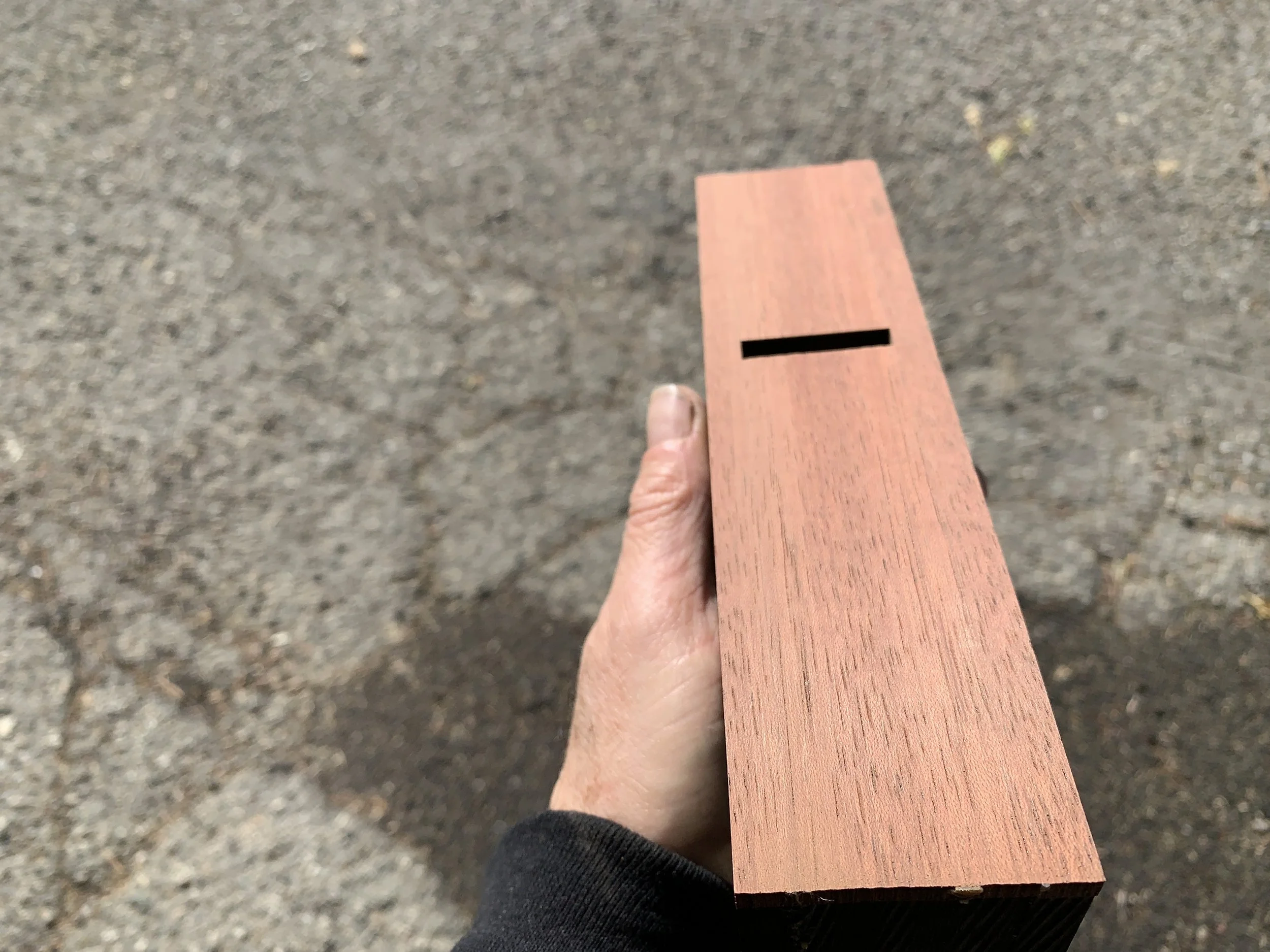
Since ebony is not abrasion resistant and can leave black marks on wood, another wood is needed for the sole. I chose jatoba as it is very hard, straight grained and a bit oily.

After glue-up, square the bottom and sides of the blanks. They are sized to be 1 1/8” wider than the blade and about an inch longer than the desired length of the plane, however, long enough to pass safely through a jointer and planer.

Additional blanks are needed for the cross-pieces and wedges. Mahogany is used here as it works well to secure the iron and wedge in place.

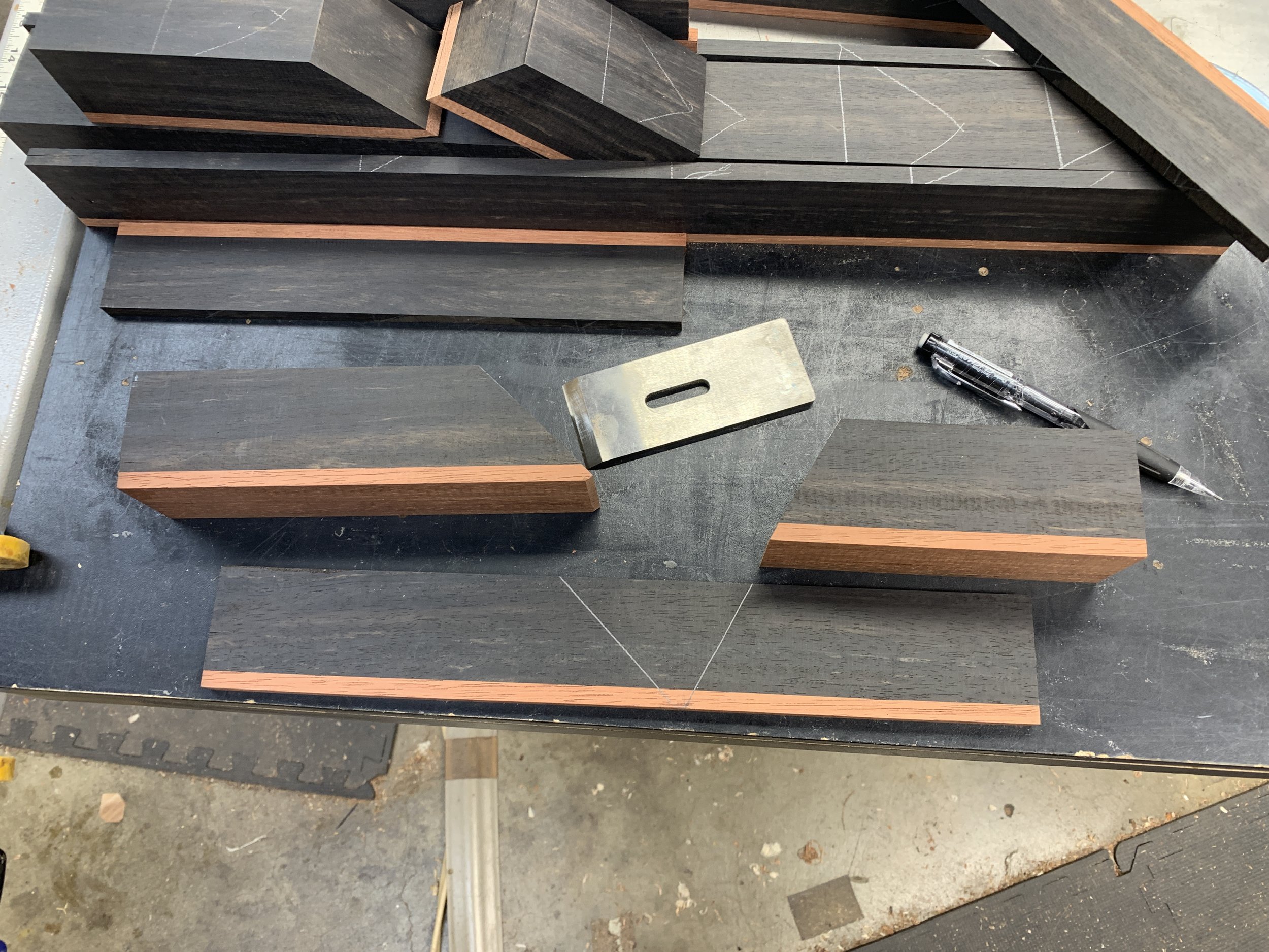
Ebony blanks with jatoba soles

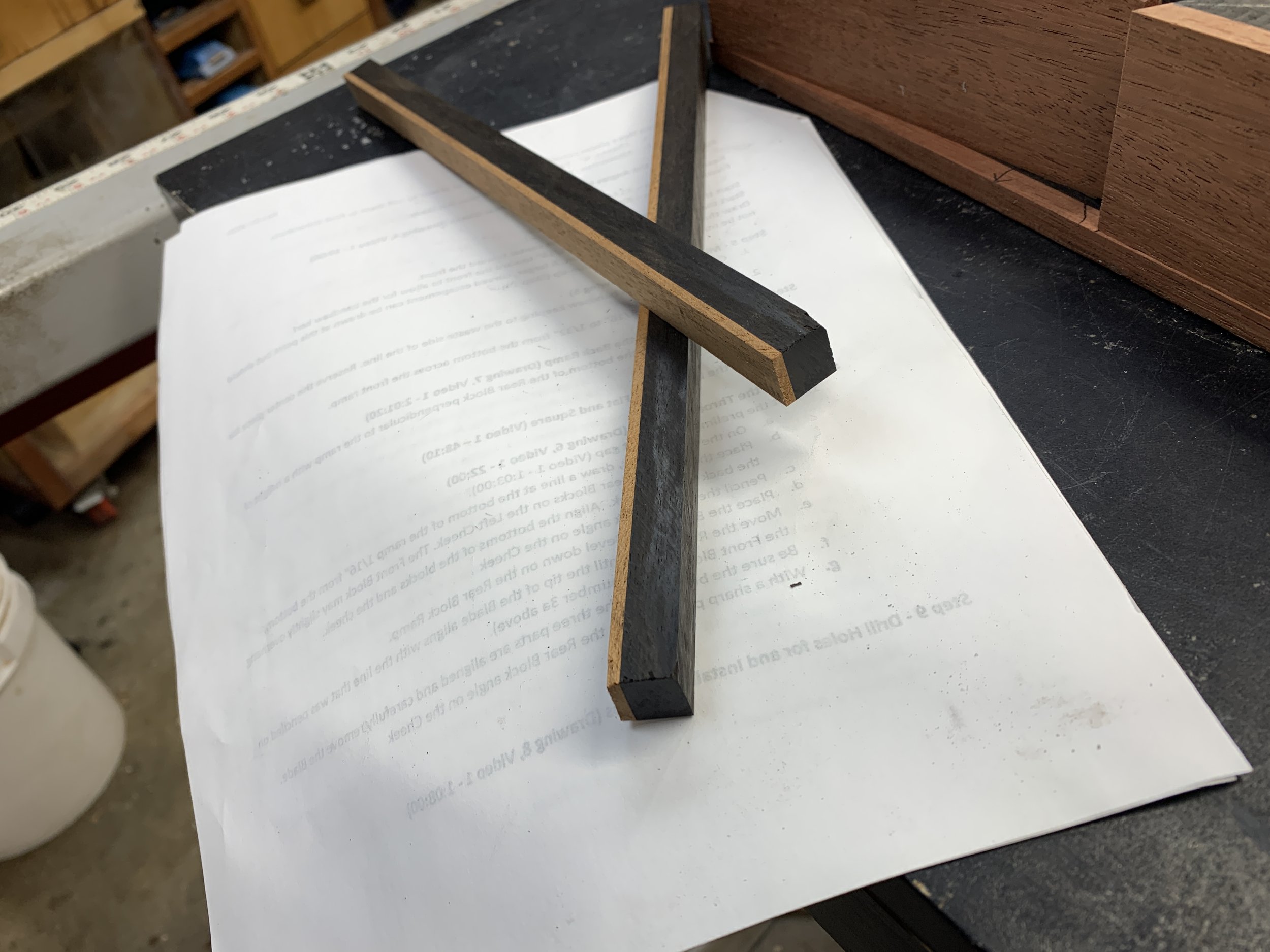
Wedge and cross-piece blanks with mahogany

Bandsaw the cheeks from the mid-section.

The mid-section should be approximately 1/16” wider than the blade after all milling done to square it and remove mill marks. The cheeks should be 1/4” to 5/16” wide after milling.

Cheeks are bandsawed being careful to leave all three pieces wide enough for final milling.

Mid-section and the inside of the cheeks jointed smooth.

Determine the mouth location and ramp angles.

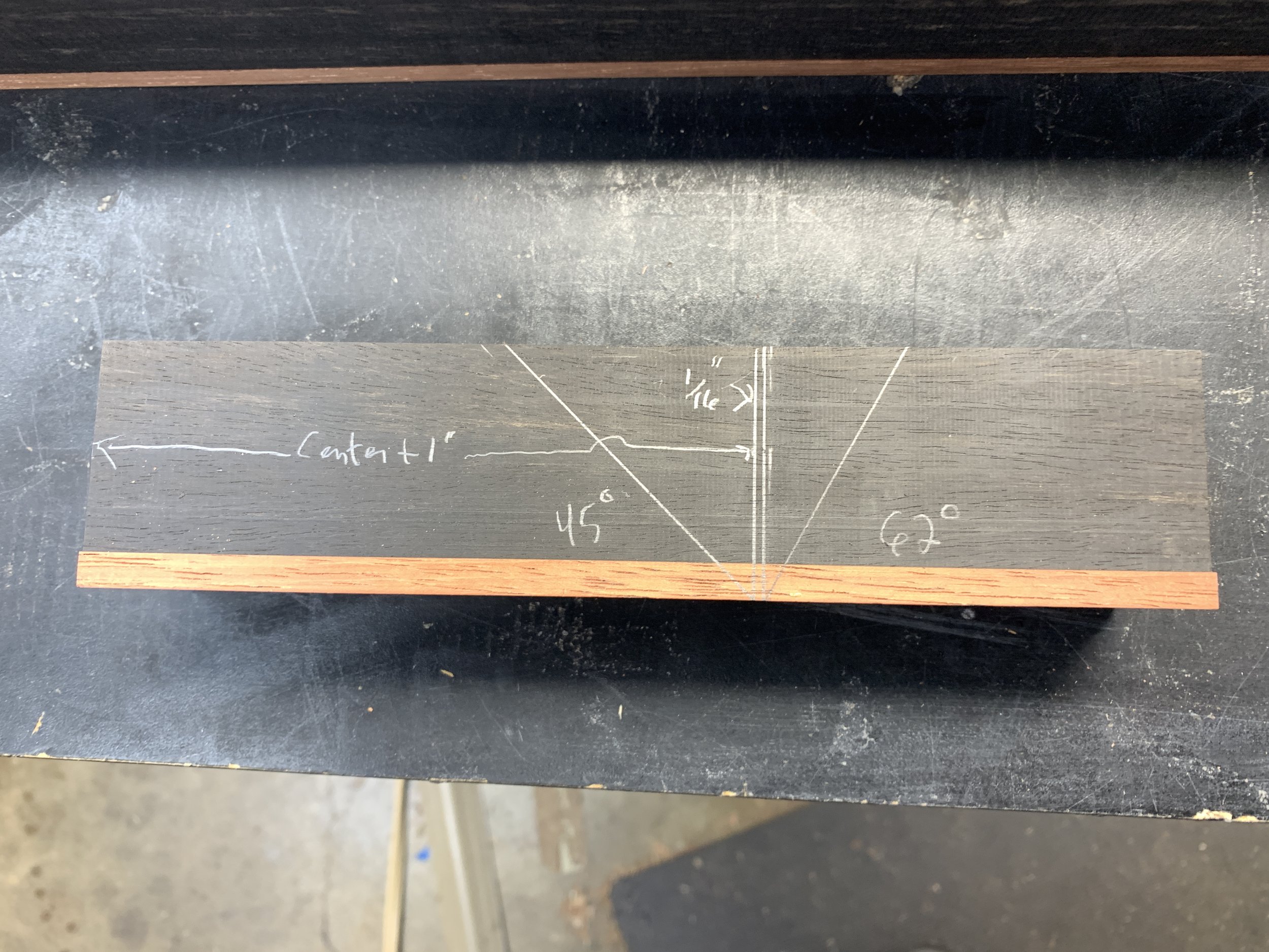
(Marked on the right side of the mid-section.)

From the back of the plane, measure to the center plus 1”. Draw a vertical line there. Draw another line 1/16” to the right. Draw a 45-degree angle from the bottom of the first line and a 62-degree angle from the bottom of the other line.

Later, I’ll go back and increase the size of the escapement. This will not be cut until just before glue-up

Mill the angles in the mid-section.

Cut close to the inside of the lines and as smoothly as possible. This will make flattening the ramp easier. Save the waste for later.

Plane or saw a 1/8” chamfer, perpendicular to the rear ramp, on the forward edge of the rear block. Also mark a line across the front ramp about 1/16” from the bottom.

Planed chamfer. This prevents the ramp from chipping at the point it meets the sole.

Line drawn on front ramp about 1/16” from the bottom.

Flatten the rear ramp.

This is the most difficult, time-consuming and frustrating step in the process and ebony didn’t make it any easier. The ramp needs to be planed square to the side of the block and as perfectly flat as possible. A small square can be used to determine the first requirement. The second can be determined by placing a 6” combination square on the ramp and twisting it back and forth. This is checked both front to back and side to side. If you feel resistance, the ramp is flat. If the square moves freely, it is not.

Flatten the front ramp (not done for this project).

If the escapement is not going to be enlarged, flatten and smooth the front ramp so that shavings can slide easily out of the escapement.

Checking flatness.

Set the throat opening.

Lay the left cheek on its side. Place the rear block on it and align it with the back of the cheek. Place the right cheek as shown in the picture below and secure the three pieces ensuring they are aligned at the sole.

Place the blade, bevel down, on the rear ramp.

Slide the front block toward the blade until the tip of the blade aligns with the line drawn across the front ramp.

Hold the front block securely in place and remove the blade. Draw the front and rear angles on the inside of the left cheek.

Rear block aligned with left cheek. Right cheek used to align the sole. Clamped to hold securely in place.

The blade is place bevel down on the rear ramp. Front block is moved until the tip of the blade aligns with the line drawn across the front ramp.

Holding the front block in place, remove the blade and draw both angles on the inside of the left cheek.

Locate and drill holes for index dowels.

Assemble the four pieces carefully aligning the blocks with the angle lines drawn on the inside of the left cheek.

Ensure the cheeks and mid-section are flush at the sole.

Place the blade on the rear ramp to confirm the throat gap is set correctly - tip of the blade aligns with the line drawn on the front ramp.

Locate dowel hole positions. Leave at least 1/8” between the holes and the ends of the cheeks.

Drill the holes, with a drill press if possible, through the cheeks and 1/2” into the mid-section.

Drill the holes on one side and insert the pins.

Use a third clamp to keep the pieces aligned while flipping the clamps to drill the holes in the other side.

Trim the dowels with a flush-cut saw and pare flat with a chisel.

Mill a 1/2” square piece of wood for the cross pin.

Most often, the cross pin can be made from the same wood as the plane body. For contrast, good candidates are mahogany and walnut.

Cross-pin hole placement

Carefully remove the right cheek. This is a good time to round-over the flat ends of the dowels to prevent jamming during glue-up.

On the inside of the left cheek, draw a line 1 1/4” from the bottom. Align the front and rear blocks with the left cheek. Place the blade, chip breaker (without the screw) and a 3/16” spacer on the rear ramp. Place the ½” square pin against the spacer aligning the diagonal of the square pin with the line drawn 1 ¼” from the bottom. Draw the upper outline of the square pin on the left cheek. Remove the square pin and draw a line from the top of the pin outline through the line drawn 1 ¼” from the bottom. The cross pin hole is located where these lines intersect.

Draw a line on the inside of the left cheek 1 1/4” from the bottom.

Place the blade, chip breaker and a 3/16” spacer on the rear ramp.

Place the 1/2” square pin against the spacer and align its diagonal with the line drawn on the left cheek. Trace the upper outline of the square pin.

Remove the pin and draw a line down from the top of the square outline through the line drawn 1 1/4'“ from the bottom. The hole for the cross pin is located where these lines intersect.

Drill holes for the cross pin.

This is a good time to check that the drill bit is perpendicular to the drill press table.

Using a 5/16” drill bit (I prefer a brad point bit and a drill press), drill the hole in the left cheek. Reassemble the plane and, with the left cheek on top, drill through the hole in it and then through the right cheek.

Counter-sink the holes on the inside of the cheeks to ease assembly during glue-up.

Drill hole in left cheek.

Reassemble the plane. Align the bit with the hole in the left cheek and drill through the right cheek.

Counter sink the holes on the inside of the cheeks.

Retrieve the waste cut-out from the mid-section and drill a few holes in it. This will be used to size the cross pin tenons.

Mill the cross pin.

There’s more than one way to cut the tenons, I use a plug-cutter and a jig to hold the cross pin vertical.

Assemble the four parts of the plane using the Index Pins. Clamp securely to bring the cheeks and blocks snugly together.
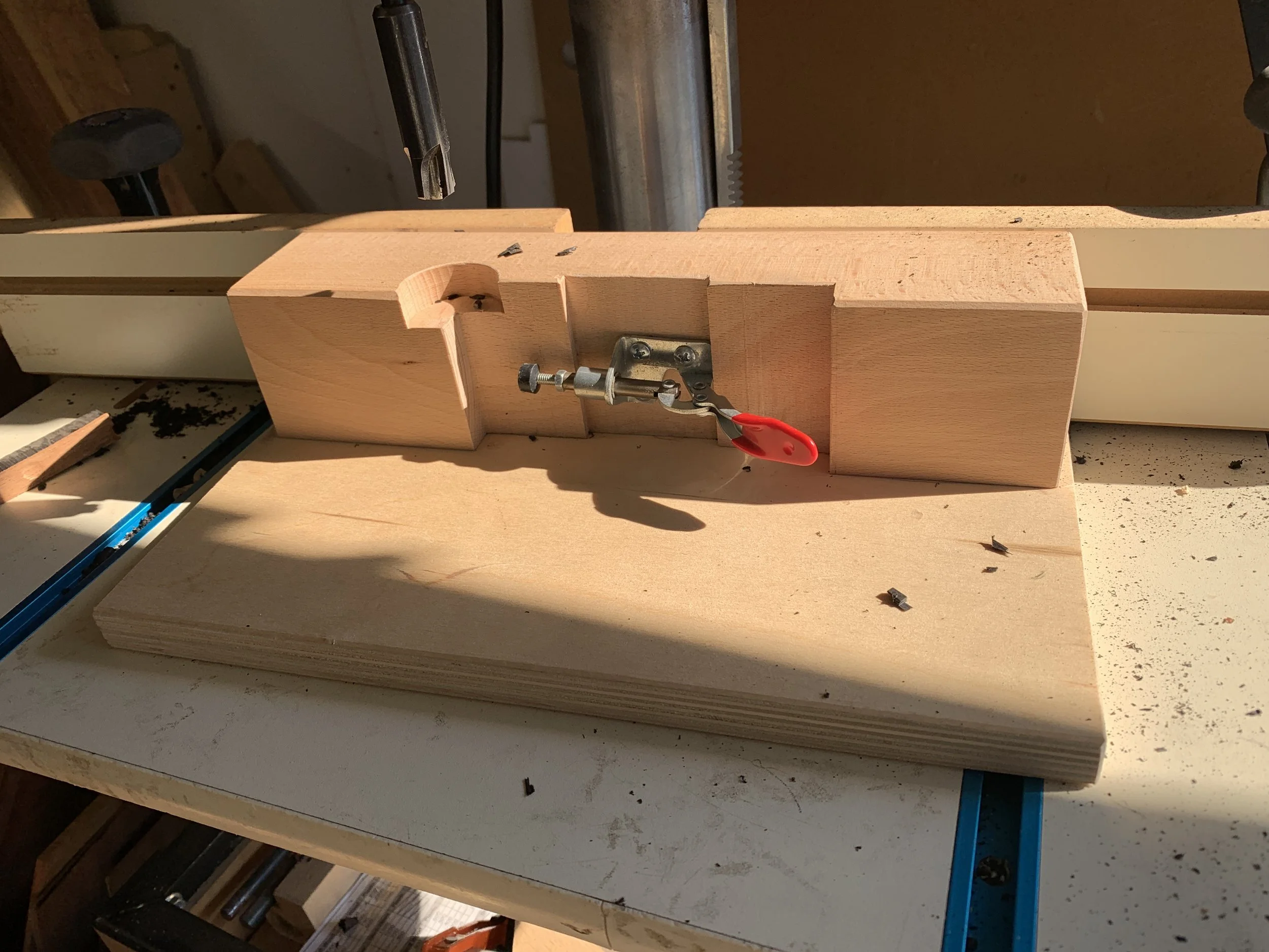
Set the cross pin across the plane and mark where the shoulders are to be milled.
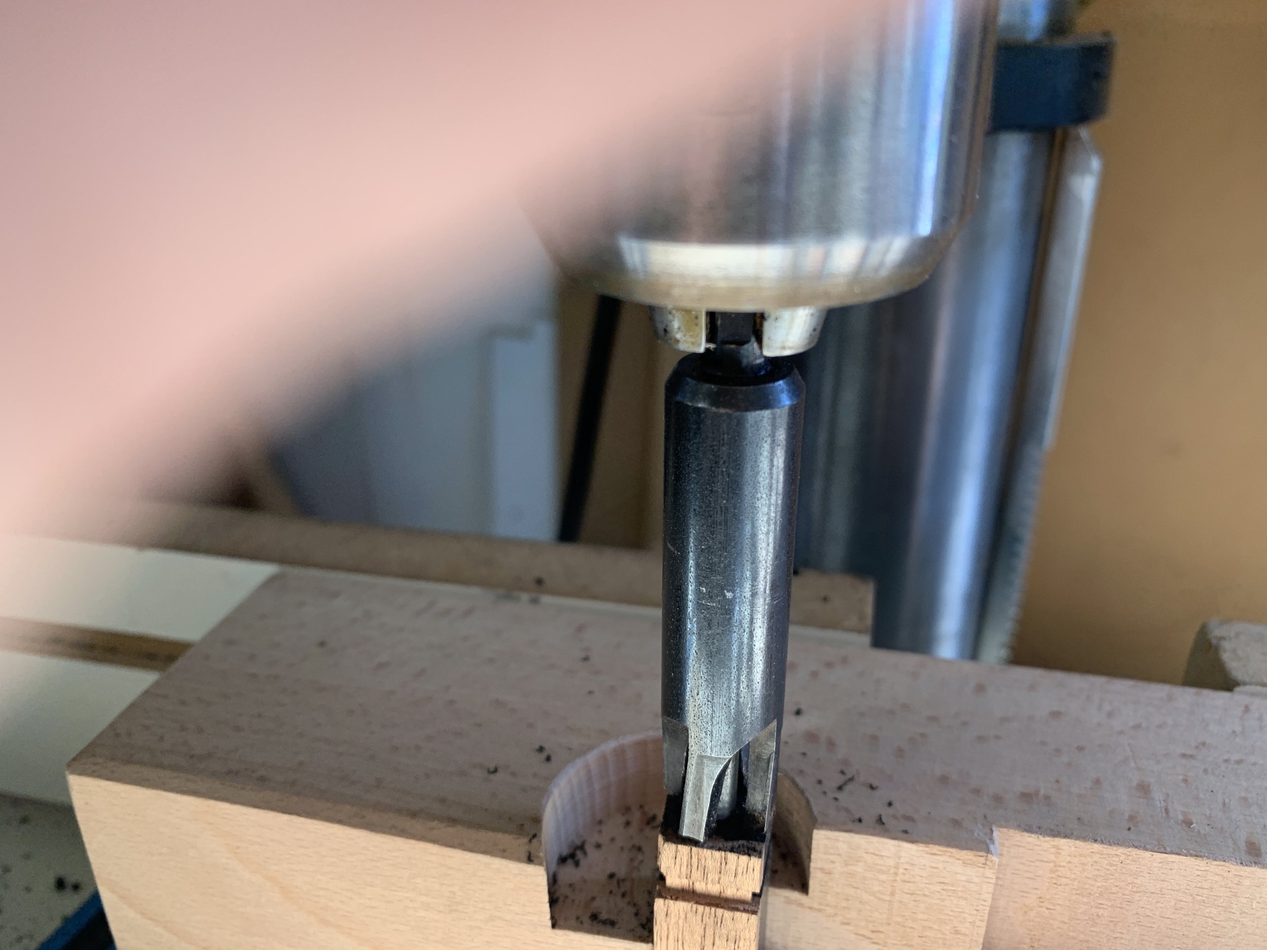
The portion of the cross pin inside the plane should be slightly smaller than the width of the midsection.

Get the tenons started using a table saw with the blade set no higher than 1/16”. Zero-in on the inside lines and cut around the pin as shown below. Cut the pin to length.

Normally, the cross pin is made from a solid piece of wood. Locate the smoothest side and mark it. This will be the side that rests on the blade.

Place the pin in the jig (or whatever means used to hold the pin vertical) with the marked side facing you. Align the plug-cutter blades so they are centered on the pin. Make a small test cut. If it looks good, complete the cut being careful to not cut too deep. Flip the pin over, keeping the marked side facing you, and cut the other tenon.

The jig to hold the cross pin vertical.

Align the plug-cutter with the pin.

A small test cut.

Complete the cut.

Flip the pin over and cut the other tenon.

Trimming the tenons.

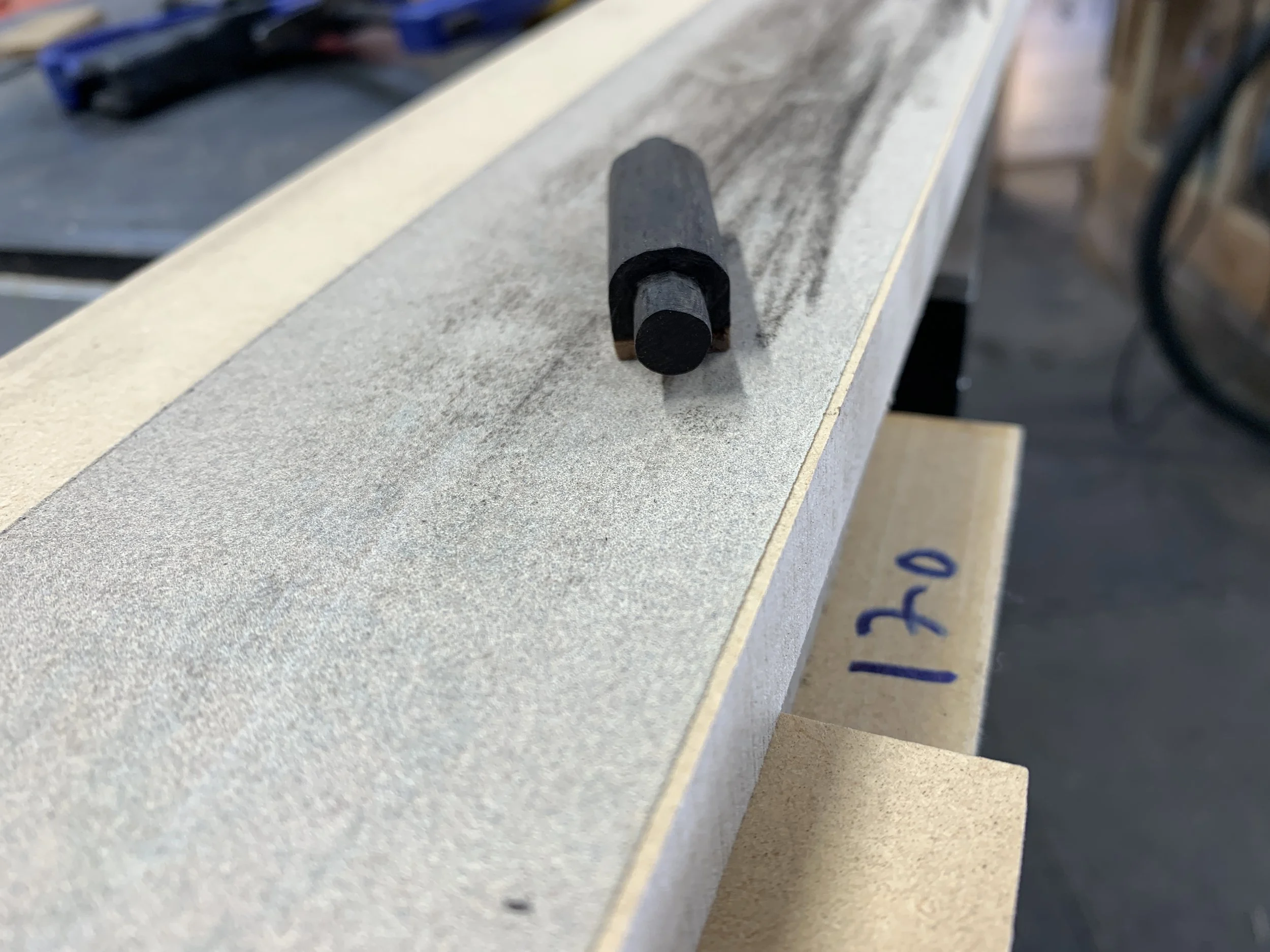
A chisel, saw, file, sandpaper or anything else you have can be used to trim the tenons to fit in the holes in the cheeks. Use the waste blocks for most of the process. Press the tenon into one of the holes and twist the cross pin. Shiny patches show where the tenon needs trimming. They should rotate easily with no wobble.

When finished with the waste block, assemble the plane with the cross pin and clamp securely. If the cross pin doesn’t move freely-but snugly, additional trimming is necessary.

Tools to trim the tenons.

Waste block.

Assembled plane clamped securely.

Locate the smoothest side of the cross pin and bevel or round-over the opposite side. This helps to locate the smooth side when setting the blade and wedge in the plane.

Mill the slot in the rear block for the chip breaker bolt.

There are many ways to do this; hand tools, router table, router and jig, etc. I use the jig designed by David Finck and a hand-held router with a pattern bit.

A center line is drawn on the rear block sole which is matched to the center line on the jig. The block is placed, ramp down, on the jig at the line marked 3/4” and clamped in place. The jig with the block is clamped upside-down in a vise. A router with a pattern bit, slightly larger than the bolt head, is used to mill the slot.

Enlarging the escapement.

This is optional. Mark the curve and shape it with a bandsaw and belt or spindle sander.

Start the curve 1/8” to 1/4” from the bottom.

Glue-up.

Sand the insides of the cheeks and ramps.

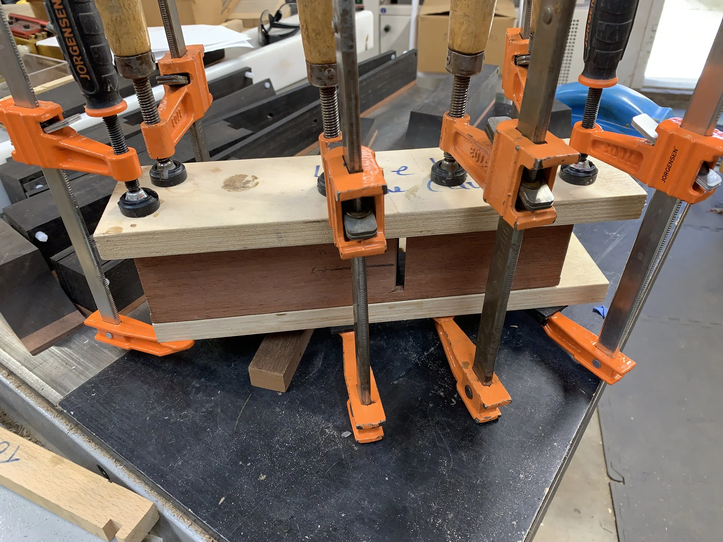
At least 6 clamps, two cauls and one alignment stick are needed. The alignment stick is thinner and longer than the mid-section and milled flat on one face and is used to ensure the sole is flat. It’s advisable to do a dry-clamping first to be sure the pieces will fit together well. When clamping the alignment stick to the sole, place the clamps close to the ramps.

Using a chisel ensure that neither the dowels nor the cross pin tenons protrude from the sides of the plane.

Dry-clamp steps: Assemble the plane and clamp the alignment stick in place ensuring it does not touch the cheeks. Place the cauls on the sides and clamp the assembly together at four of the places shown. Unclamp the alignment stick and use the clamps for the final two places.

Check the cross pin to be sure it moves freely.

If satisfied, proceed to the glue-up. Carefully remove any squeeze-out from the ramps and sole. Allow sufficient time for the glue to dry.

Smaller planes need 6 clamps. Larger planes need 2 to 4 more. The cauls and the alignment stick are longer than the plane.

Clamp placement.

Tuning and adjusting.

With the glue-up complete, tuning and adjusting can begin. This includes:

Making a temporary wedge used to put the plane under tension while flattening and squaring the sole. Making a final wedge and aligning/adjusting the mouth.

After that, all that remains is shaping the plane.

Make the temporary wedge.

The plane must be under pressure while making final adjustments to the sole. It is safer to do this without the blade in place, so a temporary wedge is used. The drawing below shows how to find the wedge angle.

Align the cross pin parallel to the back ramp. Use a ruler to measure the distance from the ramp to the bottom of the cross pin. This distance is “X” in the drawing. The “rise over run” of the angle is 1/4” over 2”.

When finished, the wedge should protrude in front of the cross pin by 1/4”.

Temporary wedge made from mahogany. Start with a blank longer than needed.

Plane the angled surface flat.

Insert the wedge in the plane with a minimal amount of pressure. Try to move the wedge side-to-side. If it moves, it’s not flat. Plane where you see the wedge pivoting on the cross pin.

Going forward, a hammer or two are required. The metal hammer is used to set the wedge. It can also be used to loosen the wedge, but will mar the plane, so I use a rawhide mallet for this.

Setting the wedge.

Setting the wedge is a process of listening. Insert the wedge in the plane. Holding the plane in one hand, tap the wedge with the metal hammer. As you tap, the sound will rise in pitch. The wedge is then properly set. You may also feel the hammer bouncing off the wedge more as it sets.

The process is the same with the final wedge and blade.

To loosen the wedge, hit the back of the plane with the rawhide hammer.

Flatten and square the sole.

Place the blade, bevel down, in the plane to see how close to the sole it touches the front ramp. It’s should be around 1/16”. Using a jointer, reduce this to 1/32”, then use sandpaper to remove any milling marks.

Two things to check first: The dowels and the cross pin are not protruding from the side and the jointer fence is square.

The jointer should be set to take very thin cuts, 1/64” if possible.

Before flattening the sole.

Fence needs to be square to the table.

This is an iterative process: Secure the wedge in the plane and make a pass or two over the blades. Remove the wedge and place the blade back in the plane to check how close it is to the sole. Repeat until the blade is 1/32” from the sole.

After jointing. Note the mill marks.

Using 120 or 180 grit sandpaper on a flat surface, sand the sole to remove milling marks. Grip the plane in the middle and apply downward pressure there. Move the plane forward and come to a stop before lifting it. This process will help achieve a flat surface without rounding the ends.

After sanding.

Milling the final wedge.

The final wedge is milled in the same way as the temporary wedge but with a couple extra steps: The end sitting near the edge of the blade needs to be rounded to a sharp point and the “hammered” end needs to be rounded to avoid cracking and ease of access.

For the final wedge, place the blade and chip breaker on the back ramp before measuring distance “X”.

Final wedge angle.

After bandsawing the angle, plane the ramp flat and test it the same way as the temporary wedge. Using sandpaper or another means, round the front edge of the wedge to a knife point.

The “hammered” end of the wedge is rounded to prevent splitting, and shaped to allow easy access to the blade.

Adjust and align the throat opening.

With the blade in the plane, hold it up to a light to see where the throat needs adjustment. Using a file, as shown below, file the high spots. This is an iterative process. Go slowly and check your work often. Stop when the blade first bursts through the mouth. The goal is a very tight fit. Pressure from the wedge, when set, will open the mouth.

File the high spots.

File with at least a 5-degree angle towards the front of the plane.

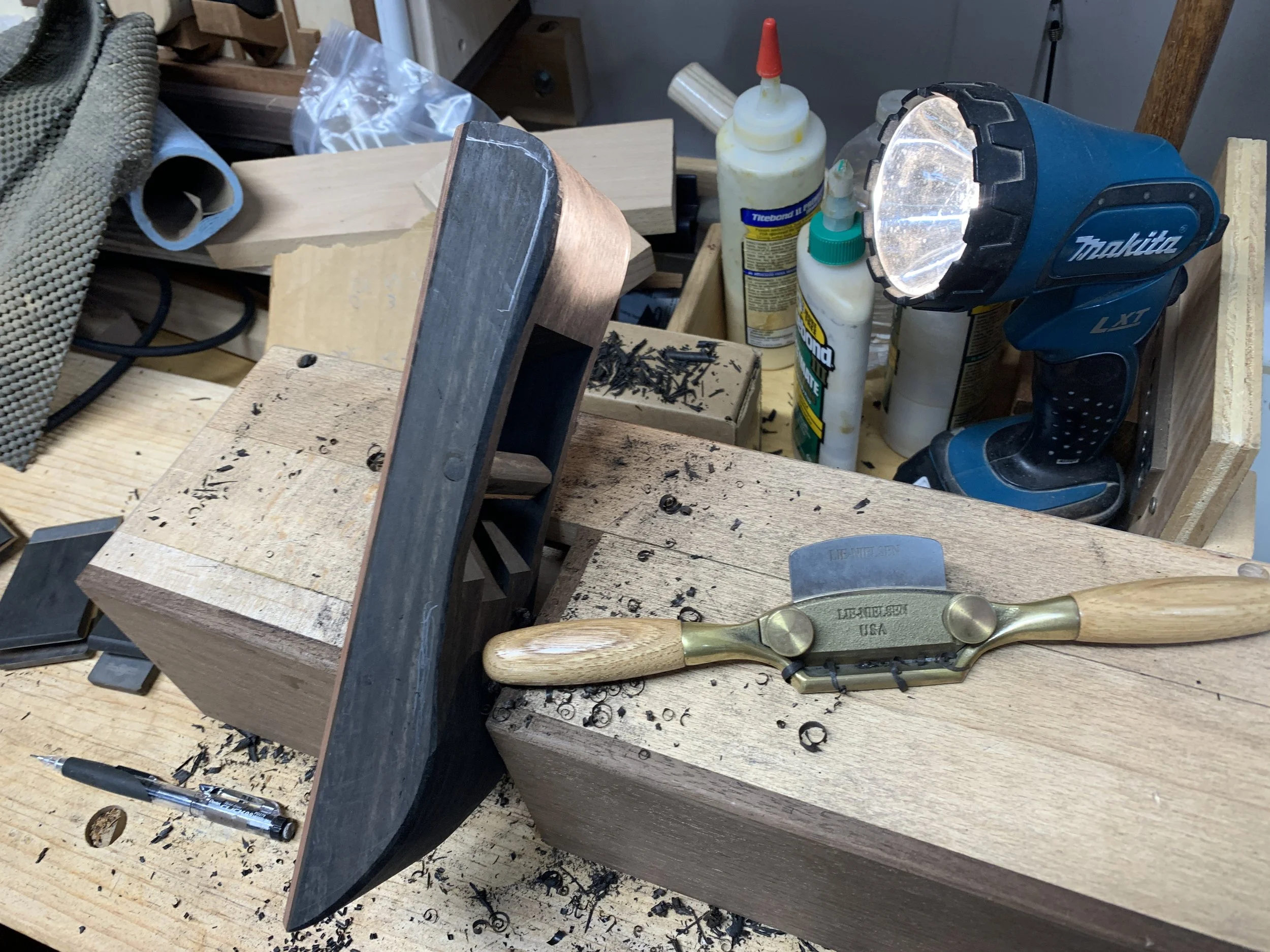
At this point, you should have a well functioning plane. Sharpen the blade and make some shavings.

Shaping the plane.

The first step is to bevel the sides of the plane at the sole. Mill to about 1/16” from the mouth. After that….

Sole sides beveled.

STAY TUNED, MORE TO COME.


To Build a Treasure Chest - Part 2, Milling the Box Parts

DETAILED DRAWINGS:

As promised, here is a link to a set of detailed drawings for the treasure chest.

We will start this blog with the basic parts having been pre-milled. Each TC box requires one each of the front, back, and box-bottom and two of the sides. See Drawing 1 for the pre-milled dimensions.

All parts should eventually be sanded with 120 grit sandpaper. This can be done before or after the following steps thought it’s much easier to sand the inside faces before assembly.

The Box: One front, one back, two sides and one box-bottom.

The Box: One front, one back, two sides and one box-bottom.

MATCH THE SIDES, DETERMINE INSIDE/OUTSIDE FACES AND ORIENTATION OF SIDES, BACK AND FRONT

The first operation in this process is one of aesthetics. It is not necessary, but will create a better looking TC.

Step 1: Match pairs of sides using grain pattern and color, determine the outside faces and which end is up.

Two examples of matched sides.

Two examples of matched sides.

Step 2: For the front and back, determine the outside faces and which end is up.

The “paired” sides must be kept together going forward. The sides will be matched with fronts and backs later.

ORDER OF OPERATIONS

It is often beneficial to group operations together for all applicable parts. For example, every part of the TC, except the box-bottom, gets a 3/16” round over on at least two edges and doing the round over operation on all these parts at the same time makes sense. (Note: The roundover is the first operation for all the parts except the sides.) The processes shown below are in the order of the drawings and not intended to be a production plan.

THE FRONT (Drawing 2)

Step 1 - 3/16” round over on all edges. Note: Throughout the drawings, a red stripe indicates where to route the round over.

Route the end grain edges first and use a push block or a jig with a sacrificial fence to avoid tear out.

Route the end grain edges first and use a push block or a jig with a sacrificial fence to avoid tear out.

For routing the small edges, parts may be grouped together but must be held securely.

For routing the small edges, parts may be grouped together but must be held securely.

Use even/consistent pressure into the table and fence.

Use even/consistent pressure into the table and fence.

Step 2 - Mill the groove for the box-bottom.

Having determined the top and inside faces of the front, mill a groove in the inside face at the bottom of the parts. The groove is 3/16” wide, 1/4” deep and 3/16” from the bottom. We mill the groove at 3/16” as the box-bottom is made from 1/4” plywood (which is really 3/16”).

There are a few ways to achieve a 3/16” groove:

  • Often, one of the outside blades of a dado set will be 3/16”

  • Make two passes on the table saw using a regular 1/8” blade

  • Use a 3/16” router bit in a router table.

Groove for the box-bottom milled in the front.

Groove for the box-bottom milled in the front.

Step 3 - Mill the rabbets for the sides
One more process is required to finish the front. That is milling the 5/8” x 1/4” deep rabbets on the inside face to join the sides to it.

Regarding dado blades: Throughout this process, we use a box-joint dado set that cuts either a 1/4” or a 3/8” dado. For dados wider than 3/8”, more than one pass is required. We use this blade because it provides a very smooth flat cut.

- Set-up the table saw and dado blade to mill a 5/8” by 1/4” dado. Add a sacrificial fence to the miter gauge.

Regarding the 5/8” specification: This is an approximation. Though the sides are milled to a 5/8” thickness, it may not be exact. Also, wood moves and dimensions change. So the 5/8” rabbets need to be adjusted to fit, as closely as possible to the thickness of the sides.

Make test cuts in a piece of scrap wood to adjust the width of the cut to match the width of the sides.

Make test cuts in a piece of scrap wood to adjust the width of the cut to match the width of the sides.

Mill the rabbets on both ends of the inside face of the front

Mill the rabbets on both ends of the inside face of the front

Sand the inside faces of the rabbets if necessary. The front is now finished.

Sand the inside faces of the rabbets if necessary. The front is now finished.

THE BACK (Drawing 3)

Step 1 - 3/16” round over on the bottom edges.

Step 2 - Mill the groove for the box-bottom.

Groove for the box-bottom milled in the back using the same dimensions as the Front.

Groove for the box-bottom milled in the back using the same dimensions as the Front.

Step 3 - Route the 1/2” round over

Set-up the 1/2” round over bit in the router table.

Set-up the 1/2” round over bit in the router table.

Place the inside face of the back against the fence with the bottom facing up and mill the round-over.

Place the inside face of the back against the fence with the bottom facing up and mill the round-over.

Sand as necessary and ease the sharp point at the top. The back is now finished.

Sand as necessary and ease the sharp point at the top. The back is now finished.

THE SIDES (Drawing 4A)

Step 1 - Route the stopped rabbet for the back.

Router table set-up

Use a 3/4” straight router bit.

Step A: Set up the bit in the router table so it will cut a 1/8” deep rabbet.

Step B: Adjust the fence so the rabbet will be 5/8” wide. Make test cuts and adjust this dimension to match the thickness of the back whose ends fit into the rabbets.

The rabbet is milled in each side to match the back. As the back has a curved top, the rabbet in the sides needs to match the curve.

Since it is a stopped-rabbet, stop-blocks need to be clamped to the router table fence at appropriate places.

Also, since the two sides are mirror images of each other, they require different set-ups for the stop-blocks.

ROUTE THE LEFT SIDE RABBET (left as in facing the front of the box)

Step A: Clamp the stop-block to the left side of the fence so the distance from the stop-block and the far edge of the router bit approximates the height of the back.

A completed back is used to position the stop-block.

A completed back is used to position the stop-block.

Step B: Make a test cut and fit the end of a back into the dado. Adjust the stop-block as necessary so when the bottoms of the two parts are flush, there should be approximately 1/8” clearance at the curved end of the rabbet.

Step C: When the stop-block is properly placed, mill all of the left sides.

Step D: Clean-up the edge with sandpaper if necessary.

Apply consistent pressure down toward the table and forward into the fence.

Apply consistent pressure down toward the table and forward into the fence.

Since the 3/4” bit leaves a small “hook” at the end of this step, after the part reaches the stop-block, pull the part out at an angle to remove the “hook.”

Since the 3/4” bit leaves a small “hook” at the end of this step, after the part reaches the stop-block, pull the part out at an angle to remove the “hook.”

Left side rabbet milled.

Left side rabbet milled.

Stopped rabbet shown with a finished back.

Stopped rabbet shown with a finished back.

ROUTE THE RIGHT SIDE RABBET

Step A: Move the stop-block to the other side of the router table fence and align as described above.

Step B: With the inside face down and the bottom of the part to the right, wedge the corner of the side against the fence and stop-block as shown.

Step B: With the inside face down and the bottom of the part to the right, wedge the corner of the side against the fence and stop-block as shown.

Step C: Keeping pressure towards the fence and the stop-block, feed the part into the router bit.

Step C: Keeping pressure towards the fence and the stop-block, feed the part into the router bit.

Step D: Feed the part to the left. Before the part moves past the router bit, add a backer-block to prevent tear-out.

Step D: Feed the part to the left. Before the part moves past the router bit, add a backer-block to prevent tear-out.

Both rabbets are milled.

Both rabbets are milled.

Step 2 - Mill the groove for the box bottom

Using a one of the techniques described above, mill a 3/16” groove in the inside face at the bottom of the sides. The groove is 1/4” deep and 3/16” from the bottom of the parts.

Milling the groove in the sides is a bit tricky as the two sides are not identical, but mirror images.

Step A: Hold the paired sides together with the bottom toward the table saw fence.

Step A: Hold the paired sides together with the bottom toward the table saw fence.

Step B: Separate the parts so the inside faces are pointed down.

Step B: Separate the parts so the inside faces are pointed down.

Step C: Place the parts on the table saw with the inside face down and the bottom against the fence.

Step C: Place the parts on the table saw with the inside face down and the bottom against the fence.

Step D: Mill the groove, one part at a time using the same dimensions as the Front.

Step D: Mill the groove, one part at a time using the same dimensions as the Front.

The end result.

The end result.

COMPLETING THE SIDES (Drawing 4B)

Step 3 - Route the 3/4” round over

To allow the lid to open properly, the top rear corner of the sides needs to be rounded-over.

Step A: Set-up a 3/4” round-over router bit in the router table.

Step B: With the back end of the side against the fence and the top of the side on the router table, feed both the left and right sides through the router bit. Use a push block or a jig with a sacrificial fence.

Step B: With the back end of the side against the fence and the top of the side on the router table, feed both the left and right sides through the router bit. Use a push block or a jig with a sacrificial fence.

IMG_3697.JPG
The result.

The result.

Step 4 - Drill the 1/4” hole for the hinge dowel pin

Drill a 1/4” hole in the upper rear corner of each side located 7/16” from the top and 7/16” from the rear.

Align the jig on a drill press table. Clamping the part down may provide a cleaner hole.

Align the jig on a drill press table. Clamping the part down may provide a cleaner hole.

Rotate the sides to always drill into the outside face.

Rotate the sides to always drill into the outside face.

Step 5 - 3/16” ROUND-OVER OF THE SIDES

Refer to Drawing 4B for the edges to be rounded.

IMG_3706.JPG
IMG_3708.JPG
IMG_3715.JPG

MATCH THE SIDES WITH A FRONT AND BACK

As mentioned before, this is not required, but will produce a nicer looking TC.

Example of matched sides, front and back.

Example of matched sides, front and back.

IMG_2975.JPG

MILL THE BOX-BOTTOM

From 1/4” plywood, mill the box-bottoms per the dimensions noted in Drawing 1. Clean up all edges with sandpaper.

READY FOR ASSEMBLY

Refer to Part 4 of this blog for box assembly instructions. If this will be done at a later date, be sure to keep the matched sets of parts together.

Building a Box With a Parquetry Top

Some time ago, a good friend mentioned he would like to give jewelry boxes to his three granddaughters for their birthdays. Since I’m only in the middle of two other projects right now, it seemed a good time to build them. After getting quite a way into the project, the thought of documenting the build came to me. His granddaughters might like to know what it took to make their boxes. Alas, I was too far along in the process, and so gave up on the idea. But it kept nagging at me, so I started a fourth box to capture the process from the beginning.

The first step was to gather together all the diamond shapes for the parquetry that were hiding in various places in my workshop. I milled them myself, but will not go into that process here.

The first step was to gather together all the diamond shapes for the parquetry that were hiding in various places in my workshop. I milled them myself, but will not go into that process here.

Building the design.

Building the design.

The design is complete.

The design is complete.

I used hide glue to affix the tiles to a piece of 1/4” plywood. The advantage of hide glue is it has a long open-time which allows more time to make adjustments.

I used hide glue to affix the tiles to a piece of 1/4” plywood. The advantage of hide glue is it has a long open-time which allows more time to make adjustments.

Glue-up continues.

Glue-up continues.

Finished, glued-up parquetry panel. Used a wet paper towel to wipe off as much glue as possible without disturbing the alignment. Let sit overnight to dry.

Finished, glued-up parquetry panel. Used a wet paper towel to wipe off as much glue as possible without disturbing the alignment. Let sit overnight to dry.

Preliminary sanding with a random orbital sander (ROS).

Preliminary sanding with a random orbital sander (ROS).

Trimmed to size on a table saw.

Trimmed to size on a table saw.

Since I’ll be building the box to fit the top, the exact dimensions of the parquetry panel are not crucial.

Since I’ll be building the box to fit the top, the exact dimensions of the parquetry panel are not crucial.

Panel trimmed to final dimensions.

Panel trimmed to final dimensions.

Since the center diamonds are taller than the others, a sanding-mop was used to reach the areas the ROS could not.

Since the center diamonds are taller than the others, a sanding-mop was used to reach the areas the ROS could not.

Hand sanding was needed as well.

Hand sanding was needed as well.

No matter how precise I try to be when milling the diamond shapes and gluing them together, there are almost always some small spaces or gaps between them.

No matter how precise I try to be when milling the diamond shapes and gluing them together, there are almost always some small spaces or gaps between them.

The solution is to fill the gaps. I use a mixture of sanding dust and shellac. Mix a small portion of each together until they have the consistency of thick mud. Then, rub the mixture into the gaps.

The solution is to fill the gaps. I use a mixture of sanding dust and shellac. Mix a small portion of each together until they have the consistency of thick mud. Then, rub the mixture into the gaps.

Shellac dries quickly and would probably be ready to sand in a few hours. I like to let it sit overnight to be safe.

Shellac dries quickly and would probably be ready to sand in a few hours. I like to let it sit overnight to be safe.

With the panel nearly complete (just a lot more sanding), it’s time to move on to the frame for the lid and sides of the box. The lid is really just a picture frame with a parquetry design in it. The parts for the frame will be 1 1/2” wide which is pleasing to my eye. The box parts will be 2 1/2” tall because that’s the maximum height the jig used to mill the mitered (45 degree) corners can handle.

Milled parts for the frame and sides. Before mitering the corners, there are a couple operations to do first. They are 1) saw a groove in the frame parts to receive the mosaic, 2) route bevels on all the corner edges for decorative purposes as well …

Milled parts for the frame and sides. Before mitering the corners, there are a couple operations to do first. They are 1) saw a groove in the frame parts to receive the mosaic, 2) route bevels on all the corner edges for decorative purposes as well as easing sharp edges.

The groove in the frame parts is cut on a table saw with a 1/4” dado blade. The first cut is centered and additional cuts are made by moving the fence away from the blade until it is wide enough to snugly fit over the panel.

Before any more milling is done, arrange the parts in the order you like best; which side up / which end out. The wood used here has a fairly consistent look so this step is not as important as it would be if highly-figured wood were used.

Before any more milling is done, arrange the parts in the order you like best; which side up / which end out. The wood used here has a fairly consistent look so this step is not as important as it would be if highly-figured wood were used.

Align the fence to center the dado blade.

Align the fence to center the dado blade.

The groove fits snugly over the panel.

The groove fits snugly over the panel.

A router, whether installed in a table or not, is an incredibly versatile tool which can mill an infinite number of profiles. For these boxes, I chose to use only a 45 degree router bit and have kept the lines simple and clean.

The first step is to route a small bevel on all corners of the frame and sides.

The first step is to route a small bevel on all corners of the frame and sides.

The bit is raised over a few passes to reach the desired height.

The bit is raised over a few passes to reach the desired height.

Final frame profile.

Final frame profile.

Next, we move on to cutting the mitered corners to form the frame and box. A miter (at least in woodworking) is a 45 degree angle. Two mitered parts will fit together to form a 90 degree, right-angled corner. However, it is quite difficult to cut a perfect 45 degree angle and if they aren’t perfect, there will be gaps. There are a few solutions. Here’s the one I use:

The concept behind this sled is that the two joining parts do not need to each be exactly 45 degrees, their angles just need to add up to 90 degrees. The fence, the darker wood, is a right-angle (90 degrees) and it’s aligned to the blade so as to cu…

The concept behind this sled is that the two joining parts do not need to each be exactly 45 degrees, their angles just need to add up to 90 degrees. The fence, the darker wood, is a right-angle (90 degrees) and it’s aligned to the blade so as to cut as close to 45 degrees as possible. One of the joining parts is cut on the left side and the other on the right. So, if one side is 44 degrees, the other will be 46 degrees and they will form a 90 degree corner.

To keep the parts organized, a piece of tape is adhered to one end of each part and the first cut is made on the left side of the sled.

To keep the parts organized, a piece of tape is adhered to one end of each part and the first cut is made on the left side of the sled.

The approximate length of the part is determined by placing it on the panel.

The approximate length of the part is determined by placing it on the panel.

The other end of the part (without tape) is then cut on the right side of the sled. The first cut is long, and a series of small cuts are made until the part is the right size.

The other end of the part (without tape) is then cut on the right side of the sled. The first cut is long, and a series of small cuts are made until the part is the right size.

The right size has been reached when the frame part is slightly longer than the panel at both ends. Once that is reached, the opposite frame part can be cut to the same length.

The right size has been reached when the frame part is slightly longer than the panel at both ends. Once that is reached, the opposite frame part can be cut to the same length.

The two adjoining sides are milled in the same manner.

The two adjoining sides are milled in the same manner.

The finished frame. Ready for sanding and then glue-up.

The finished frame. Ready for sanding and then glue-up.

The box sides are mitered the same way as the frame, except that they stand on end. They also need a groove on the inside for the bottom piece of plywood. I should have done this when milling the groove in the frame parts, but didn’t think of it then. Oh well. Just another blade switch-out.

First miter cut on the left side of the sled.

First miter cut on the left side of the sled.

The second miter is cut on the right side of the sled.

The second miter is cut on the right side of the sled.

I want the box to be even with the back of the frame (to facilitate attaching hinges), and 1/4” shorter than the three other sides. Instead of measuring, I just used 1/4” set-up blocks to find the right size.

I want the box to be even with the back of the frame (to facilitate attaching hinges), and 1/4” shorter than the three other sides. Instead of measuring, I just used 1/4” set-up blocks to find the right size.

All four sides cut to size.

All four sides cut to size.

Using set-up blocks to set up the blade for cutting the groove in the sides. 1/4” deep and 3/16” from the bottom.

Using set-up blocks to set up the blade for cutting the groove in the sides. 1/4” deep and 3/16” from the bottom.

The grooves.

The grooves.

Before gluing up the frame and sides, sand them with the random orbital sander and hand-sanding blocks starting at 120 grit, then 150 and finally 180. Also need to find a nice piece of 1/4” plywood and mill it to size for the bottom.

Before gluing up the frame and sides, sand them with the random orbital sander and hand-sanding blocks starting at 120 grit, then 150 and finally 180. Also need to find a nice piece of 1/4” plywood and mill it to size for the bottom.

Lid frame and panel ready for glue-up.

Lid frame and panel ready for glue-up.

Apply a smooth coat of glue to all the mating faces and a drop of glue in the groove of two opposing sides to hold the panel in place.

Apply a smooth coat of glue to all the mating faces and a drop of glue in the groove of two opposing sides to hold the panel in place.

There are many ways to clamp something like this. I prefer band clamps.

There are many ways to clamp something like this. I prefer band clamps.

When measuring for the bottom plywood, allow about 1/8” of clearance. This side will be cut to 8 3/8”. The adjoining side is 8 9/16”.

When measuring for the bottom plywood, allow about 1/8” of clearance. This side will be cut to 8 3/8”. The adjoining side is 8 9/16”.

Dry fit the box together. The bottom should move slightly in all directions, but not enough for an opening to show.

Dry fit the box together. The bottom should move slightly in all directions, but not enough for an opening to show.

As with the lid frame, put a drop of glue into two opposing sides and then an even coat of glue on all mating surfaces.

As with the lid frame, put a drop of glue into two opposing sides and then an even coat of glue on all mating surfaces.

Assemble and clamp the box with the band clamp and remove any glue squeeze-out on the inside with a straw or a wet cloth. Use a wet cloth to remove any other squeeze-out from the box.

Assemble and clamp the box with the band clamp and remove any glue squeeze-out on the inside with a straw or a wet cloth. Use a wet cloth to remove any other squeeze-out from the box.

Allow the lid and box to dry overnight.

Allow the lid and box to dry overnight.

For many woodworking joints, glue is sufficient by itself to hold them together. However, miter joints need additional support because they are joining end grain to end grain of the wood. End grain is porous and absorbs glue, weakening its ability to hold. There are, as always, a few solutions. My preference is using “keys” which are thin strips of wood that fit snugly and are glued into slots cut into the corners of the lid and box.

This is the jig used to cut the slots in the lid and box.

This is the jig used to cut the slots in the lid and box.

The lid is secured in the jig and each corner is passed through the saw blade.

The lid is secured in the jig and each corner is passed through the saw blade.

The results.

The results.

Here, the box is secured in the jig.

Here, the box is secured in the jig.

For this box, two keys are are sufficient to hold it together. However, for decorative purposes, more could have been used and even cut at an angle.

For this box, two keys are are sufficient to hold it together. However, for decorative purposes, more could have been used and even cut at an angle.

I had some thin strips of ebony on the shelf. First they were sanded to a thickness that fit snugly into the slots and then hand-sawed to length.

I had some thin strips of ebony on the shelf. First they were sanded to a thickness that fit snugly into the slots and then hand-sawed to length.

The keys.

The keys.

The keys are glued into the slots and left to dry overnight.

The keys are glued into the slots and left to dry overnight.

Once the glue is dry, the keys are trimmed using a saw designed to cut close to the wood without cutting into it.

Once the glue is dry, the keys are trimmed using a saw designed to cut close to the wood without cutting into it.

After sawing, the keys will be sanded flush.

After sawing, the keys will be sanded flush.

Sanded keys.

Sanded keys.

And now… hinges.

I used to call installing hinges the bane of my woodworking existence. But fortunately, while watching a recent woodworking video, I learned how to build a jig that makes the process much easier.

The locations of the hinges are marked on the box, the jig is clamped to the box and the box and jig are clamped to a bench.

The locations of the hinges are marked on the box, the jig is clamped to the box and the box and jig are clamped to a bench.

The notch for the hinge is routed into the box using a hand-held router with a pattern bit. A pattern bit has a bearing the same size as the blades so it will follow the shape of the notch in the jig.

The notch for the hinge is routed into the box using a hand-held router with a pattern bit. A pattern bit has a bearing the same size as the blades so it will follow the shape of the notch in the jig.

The bearing rides along the inside walls of the jig.

The bearing rides along the inside walls of the jig.

One place a round bearing can’t reach is into corners.

One place a round bearing can’t reach is into corners.

The remaining wood us chiseled out by hand.

The remaining wood us chiseled out by hand.

The final result. No gaps between the wood and hinge.

The final result. No gaps between the wood and hinge.

The next step is to transfer the hinge locations to the lid. This requires precision, so a knife is used to mark them.

The next step is to transfer the hinge locations to the lid. This requires precision, so a knife is used to mark them.

The same process is used as before: routing and then chiseling.

The same process is used as before: routing and then chiseling.

I couldn’t be happier with the results.

I couldn’t be happier with the results.

The hinges used here are brass and come with brass screws. Since brass is a soft metal, a steel screw is used to pre-thread the holes.

The hinges used here are brass and come with brass screws. Since brass is a soft metal, a steel screw is used to pre-thread the holes.

A small amount of wax, or other lubricant, is applied to the screw before each use. This allows the screw to penetrate more easily and prevent the wood from splitting.

A small amount of wax, or other lubricant, is applied to the screw before each use. This allows the screw to penetrate more easily and prevent the wood from splitting.

After pre-drilling and threading the center hole for each hinge, the lid and box are joined. If the results are satisfactory, the process can continue.

After pre-drilling and threading the center hole for each hinge, the lid and box are joined. If the results are satisfactory, the process can continue.

The remaining holes are drilled and threaded. It’s important to find the right size drill bit; too small and it’s difficult to thread and the wood may split, too large and the screws won’t hold. Once completed, the hinges are removed so the box can …

The remaining holes are drilled and threaded. It’s important to find the right size drill bit; too small and it’s difficult to thread and the wood may split, too large and the screws won’t hold. Once completed, the hinges are removed so the box can receive final sanding and finishing.

There are very many ways to finish wood, from simple to complicated. Since finishing is not one of my strong points, I like to keep it simple. These boxes will be finished with boiled linseed oil (BLO), a finish that has been used for centuries. It is a simple process: wipe on a thick coat, let sit for 10 - 15 minutes, wipe off. Allow to dry overnight and then repeat the process again until the finish is satisfactory.

Ready to apply the first coat of BLO.

Ready to apply the first coat of BLO.

The first coat has been applied and wiped off. It will sit over night and then receive another coat.

The first coat has been applied and wiped off. It will sit over night and then receive another coat.

Added a chain to keep the lid from falling back and a coat of paste wax applied to the top and sides of the box … and the boxes are done.

Added a chain to keep the lid from falling back and a coat of paste wax applied to the top and sides of the box … and the boxes are done.

The main wood is walnut. The diamonds are ebony, bloodwood and black limba.

The main wood is walnut. The diamonds are ebony, bloodwood and black limba.

The main wood is shedua. The diamonds are bloodwood, yellowheart, black limba (light brown) and katalox (dark brown).

The main wood is shedua. The diamonds are bloodwood, yellowheart, black limba (light brown) and katalox (dark brown).

The main wood is European beech. The diamonds are bloodwood, yellowheart and shedua.

The main wood is European beech. The diamonds are bloodwood, yellowheart and shedua.

A few things to remember:

  • Boiled linseed oil is not a protective finish, so the boxes are subject to scratches and damage from heat or water.

  • The finish will dull over time. I don’t suggest using furniture polish, just wipe with a barely damp cloth to remove dust. One of the nice aspects of BLO is that additional coats can be applied any time - even years later.

  • Most woods darken over time if exposed to light. Several of the woods used in these boxes will get darker. Aside from keeping them in a dark closet, there’s not much that can be done about it.

  • And finally, young ladies, I hope you enjoy your grandfather’s gifts.

To Build a Treasure Chest - Part 1

The San Fernando Valley Woodworkers Club has been making wooden toys and donating them to charities that care for children, in various forms of need, for over thirty years. I’ve been with the club for ten years and for at least five of them have been on the team that builds treasure chests and a smaller box for older kids that we call the teen box.

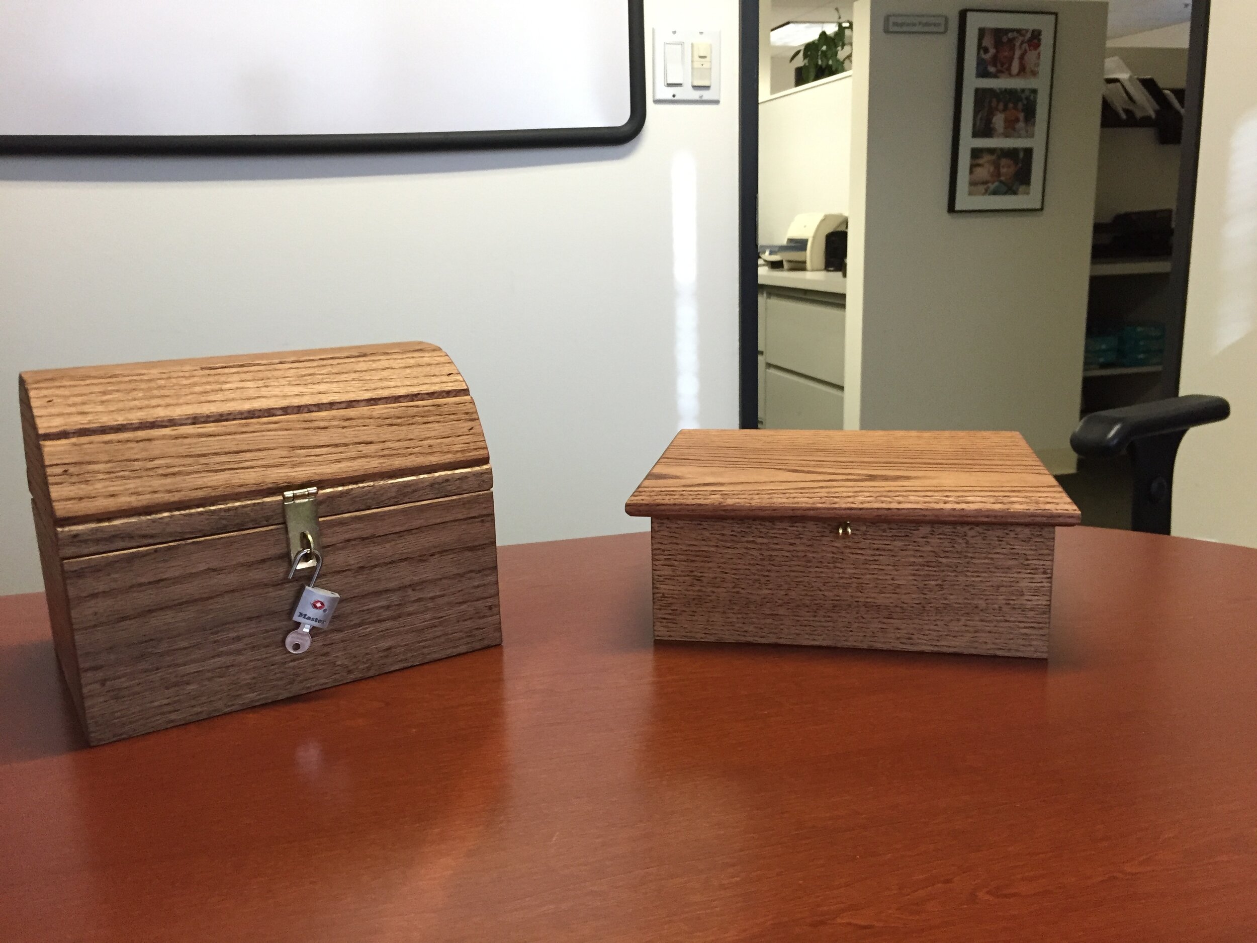
Treasure chest and Teen box. Both come with a padlock.

Treasure chest and Teen box. Both come with a padlock.

The design of the treasure chest (TC) has evolved and changed, to a greater or lesser degree, every year as we refine our processes. This blog, along with a set of detailed drawings, will describe the current process to build a TC.

Before jumping into the build, I have a couple short tales to relate:

PADLOCKS

The first year we built the boxes, we put padlocks on the TC only. Word quickly got back to us that the older kids wanted locks on their boxes, too. This may seem insignificant, but consider that many of these children are homeless or in transition and have little or no privacy. Being able to lock a box that holds their possessions is a comfort to them.

TEARJERKER

A few years ago, we received a request for a dozen TC’s from a woman who, we were told, works with troubled children. Apparently she had been getting the TC’s from another organization to which we donate, but something had changed and this was no longer happening. It was in the middle of the year and, normally, we don’t have any completed toys until November. So, a few club members got together and made a dozen for her.

One morning, another club member & I delivered the TC’s to this lady and we learned more about what she does and how she uses the TC’s.

She’s a psychologist who works with children who are dying of cancer or have a parent who is dying of cancer. Often, as patients finish their sessions with her, she gives them a TC as part of her closure process. And if the patient is a parent, they use the TC to hold the letters they’ve written for their children to open at various ages.

We were really touched and honored that a simple wooden toy we built could mean so much to someone, and in a small way, make a difference in their lives.

MOVING ON…

DRAWINGS

As with just about any woodworking project, the more accurate the milling of the parts the easier the assembly. Additionally, it can lead to less finish sanding. Part 2 of this blog will include a link to a set of detailed drawings of the TC.

THE JIGS

The TC’s can, and have been milled and assembled without jigs. The jigs were conceived, designed and evolved along with the TC design and construction. Some are as simple as a right angle glued and screwed to a piece of plywood and some are ingeniously designed.

I want to take a moment here to single out Jack Robbins for the amazing jigs he made for us. It’s easy to determine which jigs Jack built as they are described below.

Box Assembly Jig

For a jig to be useful, it does not have to be complicated. This jig’s purpose is to hold the box of the TC square as the front, back, sides and box-bottom are glued and pin-nailed together.

For a jig to be useful, it does not have to be complicated. This jig’s purpose is to hold the box of the TC square as the front, back, sides and box-bottom are glued and pin-nailed together.

Lid Assembly and Milling Jig

This is a multi-purpose jig. First, it is used to hold and clamp the lid slats in place for glue-up and second, for milling a curved rabbet in the ends of the slats.

This is a multi-purpose jig. First, it is used to hold and clamp the lid slats in place for glue-up and second, for milling a curved rabbet in the ends of the slats.

End Cap Jig

The end caps need an arc milled on them that matches the curve in the lid.

The end caps need an arc milled on them that matches the curve in the lid.

Hinge Dowel Hole Jig

A precisely placed hole is needed for the lid to open and close properly.

A precisely placed hole is needed for the lid to open and close properly.

Final Assembly Jig

This jig holds the lid and box in an aligned position for final assembly.

This jig holds the lid and box in an aligned position for final assembly.

Hasp Jig

Viewed from the opposite direction, the jig locates the holes for screws that hold the hasp in place.

Viewed from the opposite direction, the jig locates the holes for screws that hold the hasp in place.

The following blogs detail the steps we take to mill the parts and assemble the TC.

My Push Stick, My Friend

Not sure exactly how I came to this design, but it was probably by taking bits of other woodworker’s ideas. It hugs the table saw fence for smooth and controlled movement, the face moves up and down to exactly fit the board that is being cut, the face also extends forward to give added downward pressure on the board.

IMG_2699.JPG
IMG_2701.JPG
IMG_2705.JPG
Push Stick.png

Building a Rocking Chair

I saw a rather rustic rocking chair at my brother’s home in Grass Valley, CA. The lines attracted me, so I took some pictures and dimensions and decide to try my hand at designing and building one. Below are pics of the original chair and my final SketchUp drawing.

IMG_2439.JPG
Rocking Chair V3 1.png

The first step was to build a mock-up out of plywood. This was a good plan as, once together, the chair was seriously out of balance. Searching the internet, I found a short video that explained how to find a rocking chair’s center of gravity. It took a lot of experimentation to get the position of the seat & back to a place where sitting in the chair was comfortable.

IMG_2522.JPG

Milling the Rockers

To mill the rockers, I needed to know their dimensions and the radius of the compass required to draw the arc. The dimensions came from the original chair (see SketchUp drawing below) and the radius calculation was accomplished with the help of this website. The result was a radius of 39 inches. Below is also a picture of the simple compass built with a 39 inch arm.

Rocking Chair 2.png
IMG_2558.JPG

After drawing the first arc, the compass was moved up 2 inches and the second arc was drawn. The rocker was rough-cut on a bandsaw and then sanded to final dimensions using an oscillating belt sander and hand-sanding as well. It’s crucial to sand a smooth curve. It’s equally crucial that the rockers be identical, so the second rocker was milled on a router table using the first rocker as a template.

IMG_2575.JPG

Here are a few more pictures of the build.

Through mortises for the arm rests

Through mortises for the arm rests

Tenons cut on a table saw with a dado blade.

Tenons cut on a table saw with a dado blade.

IMG_2543.JPG
Half-lap joinery was used for the rest of the frame.

Half-lap joinery was used for the rest of the frame.

First complete dry assembly.

First complete dry assembly.

Since I’m going for a modern look, most of the edges will be beveled.

Slats and stretchers for the seat and back have been beveled and sanded.

Slats and stretchers for the seat and back have been beveled and sanded.

Slats are held in position with spacers.

Slats are held in position with spacers.

IMG_2670.JPG

Glue-Up

Glued-up the sides, seat & back. For the seat & back, glue was only applied to the spacers.

Dry fit to be sure it will go together smoothly.

Dry fit to be sure it will go together smoothly.

IMG_2693.JPG
The Seat

The Seat

The Back

The Back

Right & left sides glued-up

Right & left sides glued-up

Beveling edges

Beveling edges

Sides, back & seat glued-up. Just need to add the arm rests and rockers.

Sides, back & seat glued-up. Just need to add the arm rests and rockers.

IMG_2723.JPG

Confession

I’ve made lots of mistakes along the way and have recovered from or covered-up most of them. So I’m not going to point those out. There is one, however, that I must. It was mentioned earlier that a lot of time was spent with the mock-up chair to get the balance right. The problem is, when I transferred the angles to this chair and put it together, it was out of balance. To correct this, I had to shorten the front legs and raise the back. To raise the back, walnut inserts were cut and fitted to the curve of the rocker..

IMG_2730.JPG
IMG_2733.JPG
IMG_2734.JPG
IMG_2736.JPG
Gluing the rockers on

Gluing the rockers on

IMG_2741.JPG