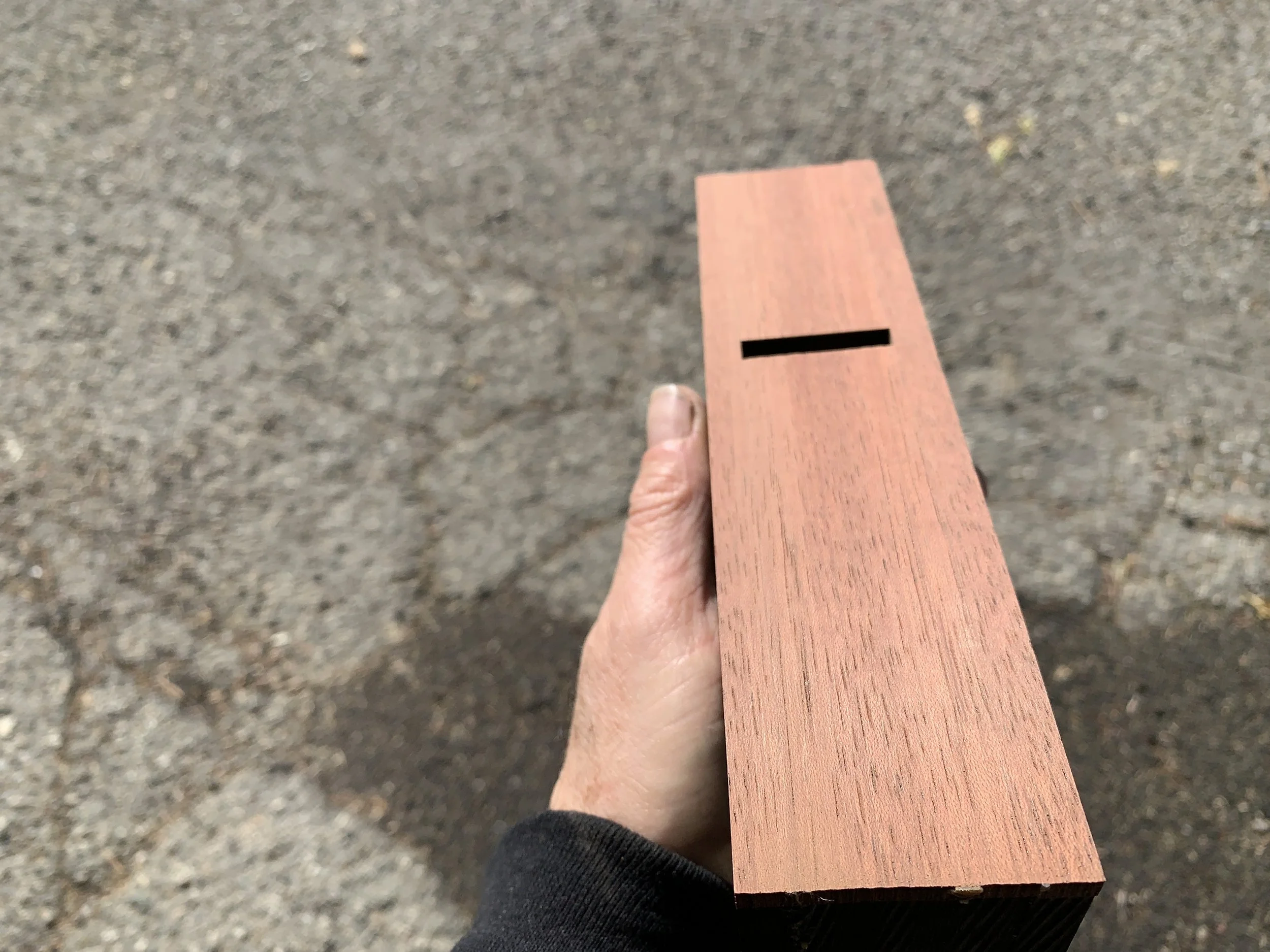
I was fortunate to come across a large ebony board and decided to make a set of hand planes from it: block plane, smoother, jack plane and jointer.
Before going further, I want to credit David Finck and his amazing book and video on how to build a Krenov plane for teaching me all I know about this. I highly recommend that anyone interested in building one of these planes spend some quality time with his video.
https://www.davidfinck.com/making-and-mastering-wood-planes/
Preparing the blanks
Since ebony is not abrasion resistant and can leave black marks on wood, another wood is needed for the sole. I chose jatoba as it is very hard, straight grained and a bit oily.
After glue-up, square the bottom and sides of the blanks. They are sized to be 1 1/8” wider than the blade and about an inch longer than the desired length of the plane, however, long enough to pass safely through a jointer and planer. Minimum height is 2 1/2”.
Additional blanks are needed for the cross-pieces and wedges. Mahogany is used here as it works well to secure the iron and wedge in place.
Ebony blanks with jatoba soles
Wedge and cross-piece blanks with mahogany
Bandsaw the cheeks from the mid-section.
The mid-section should be approximately 1/16” wider than the blade after all milling is done to square it and remove mill marks. The cheeks should be 1/4” to 5/16” wide after milling.
Cheeks are bandsawed being careful to leave all three pieces wide enough for final milling.
Mid-section and the inside of the cheeks jointed smooth.
Determine the mouth location and ramp angles
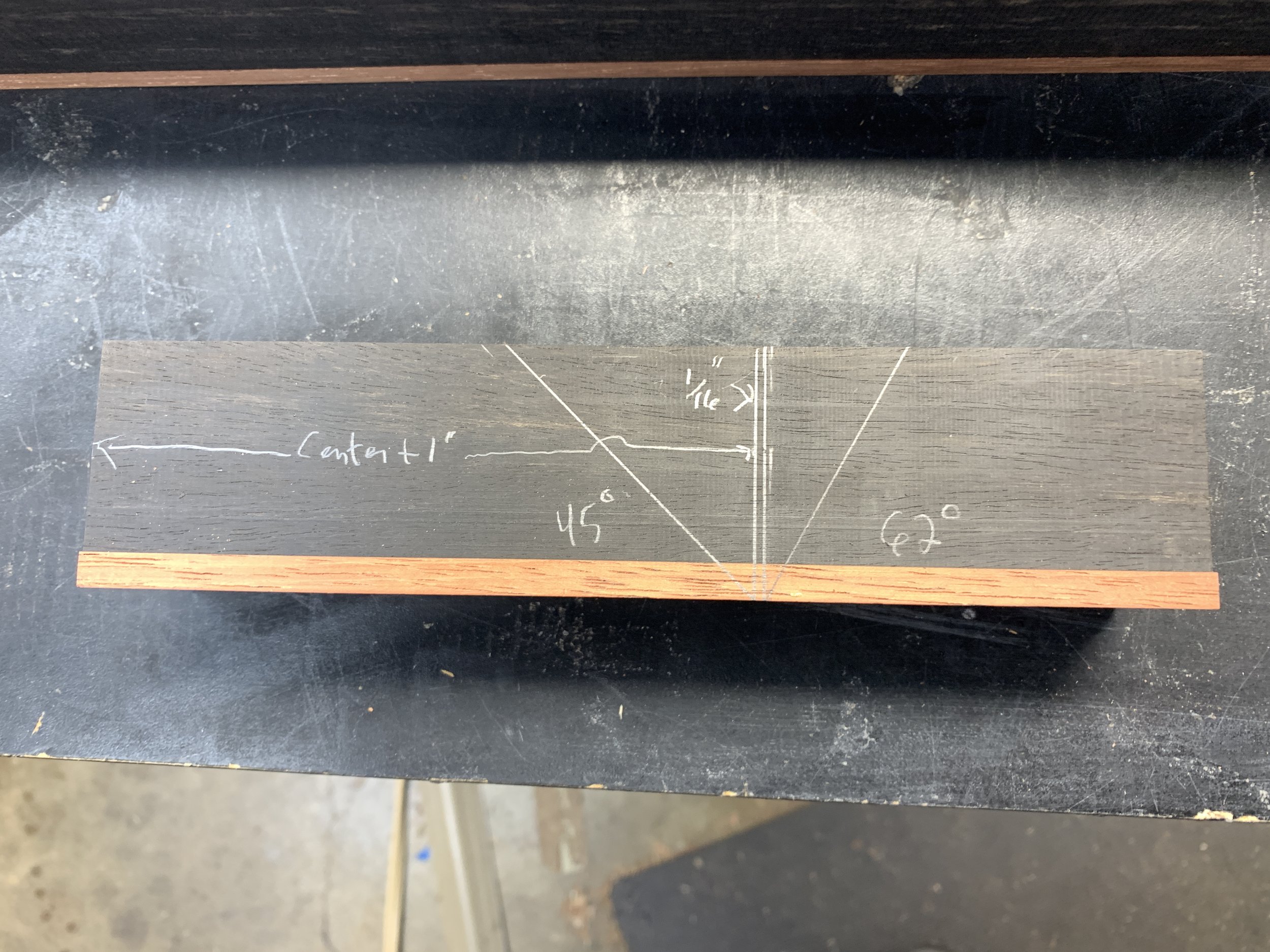
(Marked on the right side of the mid-section.)
From the back of the plane, measure to the center plus 1”. Draw a vertical line there. Draw another line 1/16” to the right. Draw a 45-degree angle from the bottom of the first line and a 62-degree angle from the bottom of the other line.
Later, I’ll go back and increase the size of the escapement. This will not be cut until just before glue-up
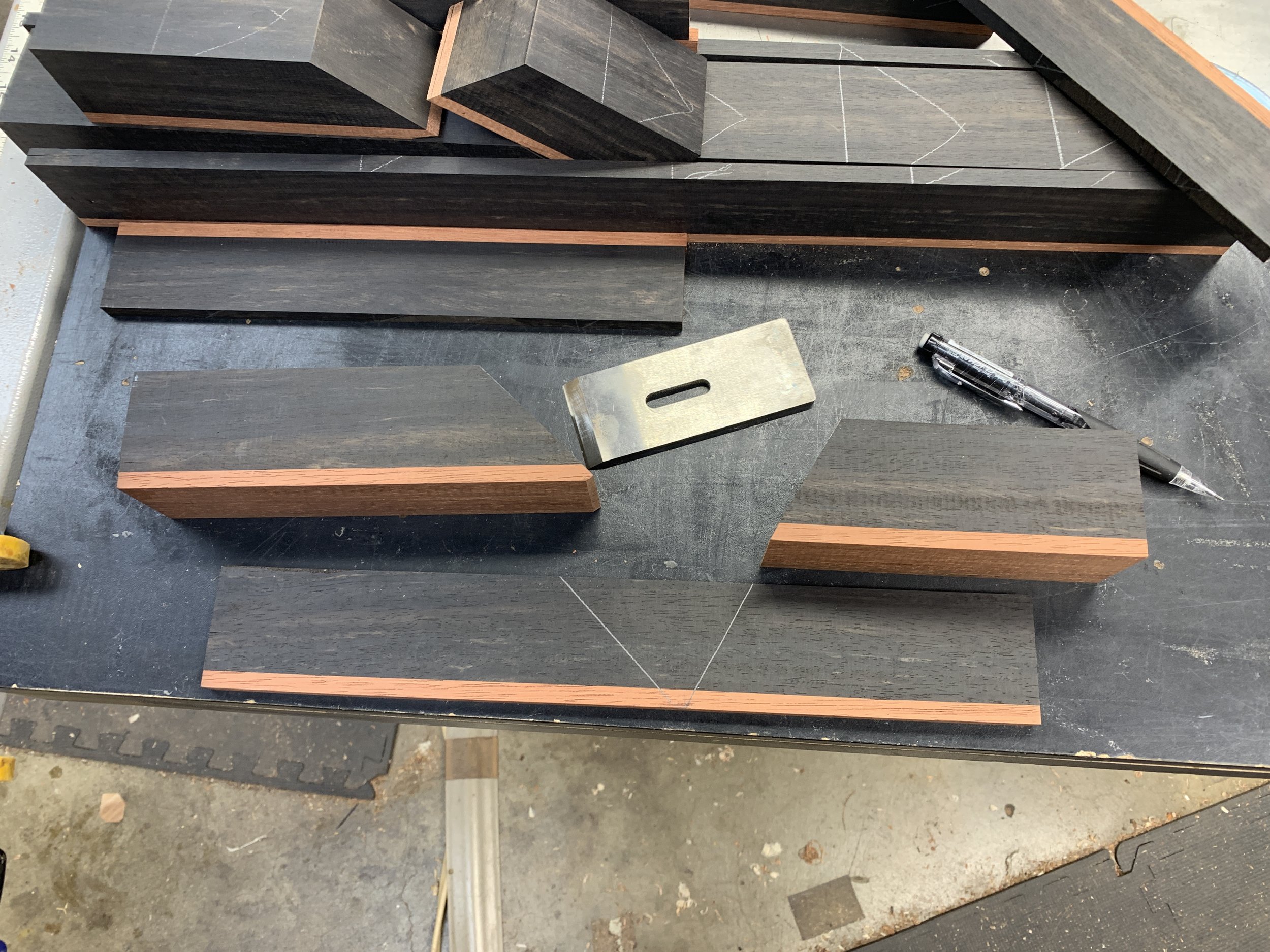
Mill the angles in the mid-section
Cut close to the inside of the lines and as smoothly as possible. This will make flattening the ramp easier. Save the waste for later.
Plane or saw a 1/8” chamfer, perpendicular to the rear ramp, on the forward edge of the rear block. Also mark a line across the front ramp about 1/16” from the bottom.
Planed chamfer. This prevents the ramp from chipping at the point it meets the sole.
Line drawn on front ramp about 1/16” from the bottom.
Flatten the rear ramp
This is the most difficult, time-consuming and frustrating step in the process and ebony didn’t make it any easier. The ramp needs to be planed square to the side of the block and as perfectly flat as possible. A small square can be used to determine the first requirement. The second can be determined by placing a 6” combination square on the ramp and twisting it back and forth. This is checked both front to back and side to side. If you feel resistance, the ramp is flat. If the square moves freely, it is not.
Flatten the front ramp (not done for this project)
If the escapement is not going to be enlarged, flatten and smooth the front ramp so shavings can slide easily out of the escapement.
Checking flatness.
Set the throat opening
Lay the left cheek on its side. Place the rear block on it and align it with the back of the cheek. Place the right cheek as shown in the picture below and secure the three pieces ensuring they are aligned at the sole.
Place the blade, bevel down, on the rear ramp.
Slide the front block toward the blade until the tip of the blade aligns with the line drawn across the front ramp.
Hold the front block securely in place and remove the blade. Draw the front and rear angles on the inside of the left cheek.
Rear block aligned with left cheek. Right cheek used to align the sole. Clamped to hold securely in place.
The blade is place bevel down on the rear ramp. Front block is moved until the tip of the blade aligns with the line drawn across the front ramp.
Holding the front block in place, remove the blade and draw both angles on the inside of the left cheek.
Locate and drill holes for index dowels
Assemble the four pieces carefully aligning the blocks with the angle lines drawn on the inside of the left cheek.
Ensure the cheeks and mid-section are flush at the sole.
Place the blade on the rear ramp to confirm the throat gap is set correctly - tip of the blade aligns with the line drawn on the front ramp.
Locate dowel hole positions. Leave at least 1/8” between the holes and the ends of the cheeks.
Drill the holes, with a drill press if possible, through the cheeks and 1/2” into the mid-section.
Drill the holes on one side and insert the pins.
Use a third clamp to keep the pieces aligned while flipping the clamps to drill the holes in the other side.
Trim the dowels with a flush-cut saw and pare flat with a chisel.
Mill a 1/2” square piece of wood for the cross pin
Most often, the cross pin can be made from the same wood as the plane body. For contrast, good candidates are mahogany and walnut.
Cross-pin hole placement
Carefully remove the right cheek. This is a good time to round-over the flat ends of the dowels to prevent jamming during glue-up.
On the inside of the left cheek, draw a line 1 1/4” from the bottom. Align the front and rear blocks with the left cheek. Place the blade, chip breaker (without the screw) and a 3/16” spacer on the rear ramp. Place the ½” square pin against the spacer aligning the diagonal of the square pin with the line drawn 1 ¼” from the bottom. Draw the upper outline of the square pin on the left cheek. Remove the square pin and draw a line from the top of the pin outline through the line drawn 1 ¼” from the bottom. The cross pin hole is located where these lines intersect.
Draw a line on the inside of the left cheek 1 1/4” from the bottom.
Place the blade, chip breaker and a 3/16” spacer on the rear ramp.
Place the 1/2” square pin against the spacer and align its diagonal with the line drawn on the left cheek. Trace the upper outline of the square pin.
Remove the pin and draw a line down from the top of the square outline through the line drawn 1 1/4'“ from the bottom. The hole for the cross pin is located where these lines intersect.
Drill holes for the cross pin
This is a good time to check that the drill bit is perpendicular to the drill press table.
Using a 5/16” drill bit (I prefer a brad point bit and a drill press), drill the hole in the left cheek. Reassemble the plane and, with the left cheek on top, drill through the hole in it and then through the right cheek.
Counter-sink the holes on the inside of the cheeks to ease assembly during glue-up.
Drill hole in left cheek.
Reassemble the plane. Align the bit with the hole in the left cheek and drill through the right cheek.
Counter sink the holes on the inside of the cheeks.
Retrieve the waste cut-out from the mid-section and drill a few holes in it. This will be used to size the cross pin tenons.
Mill the cross pin
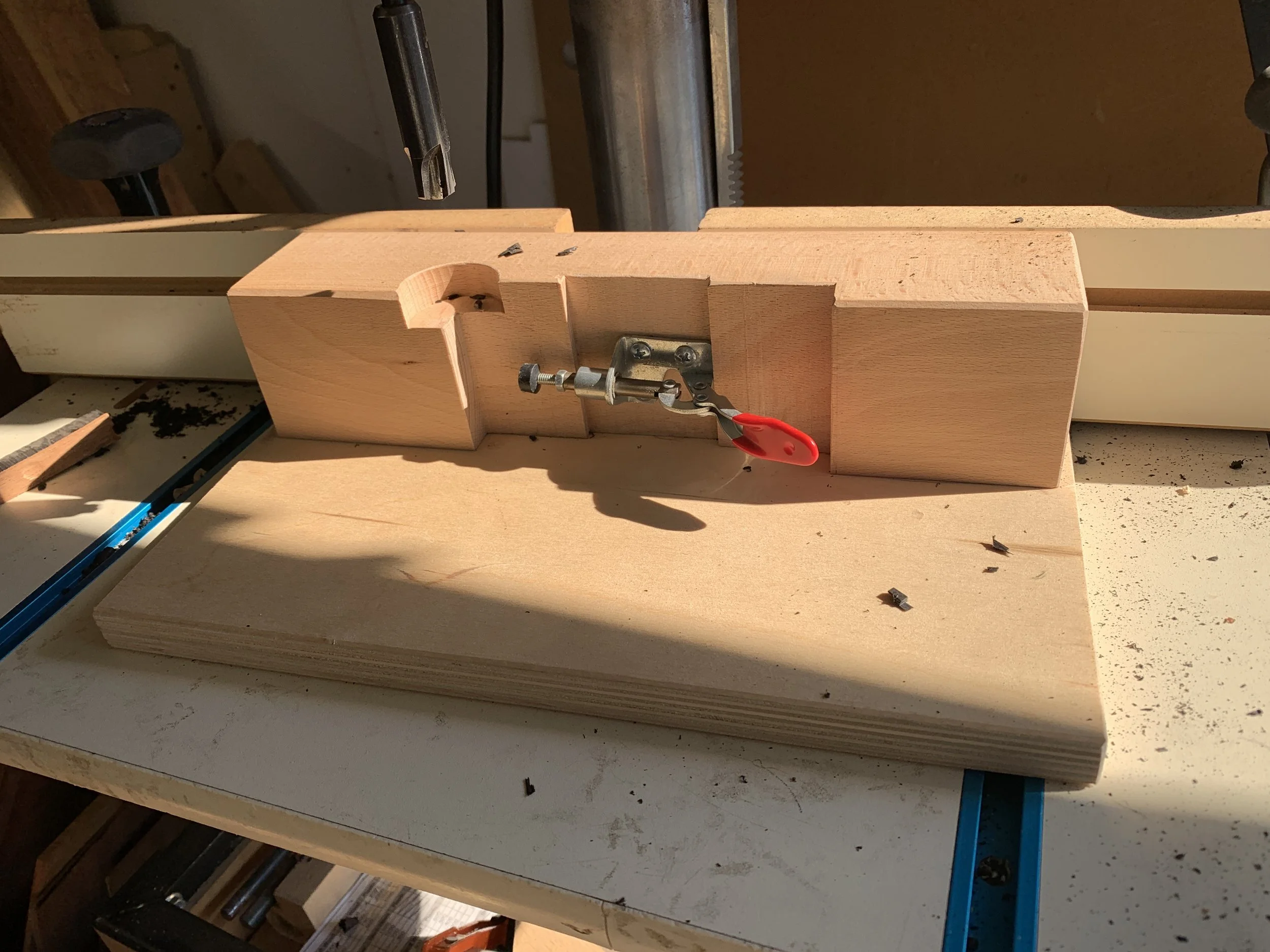
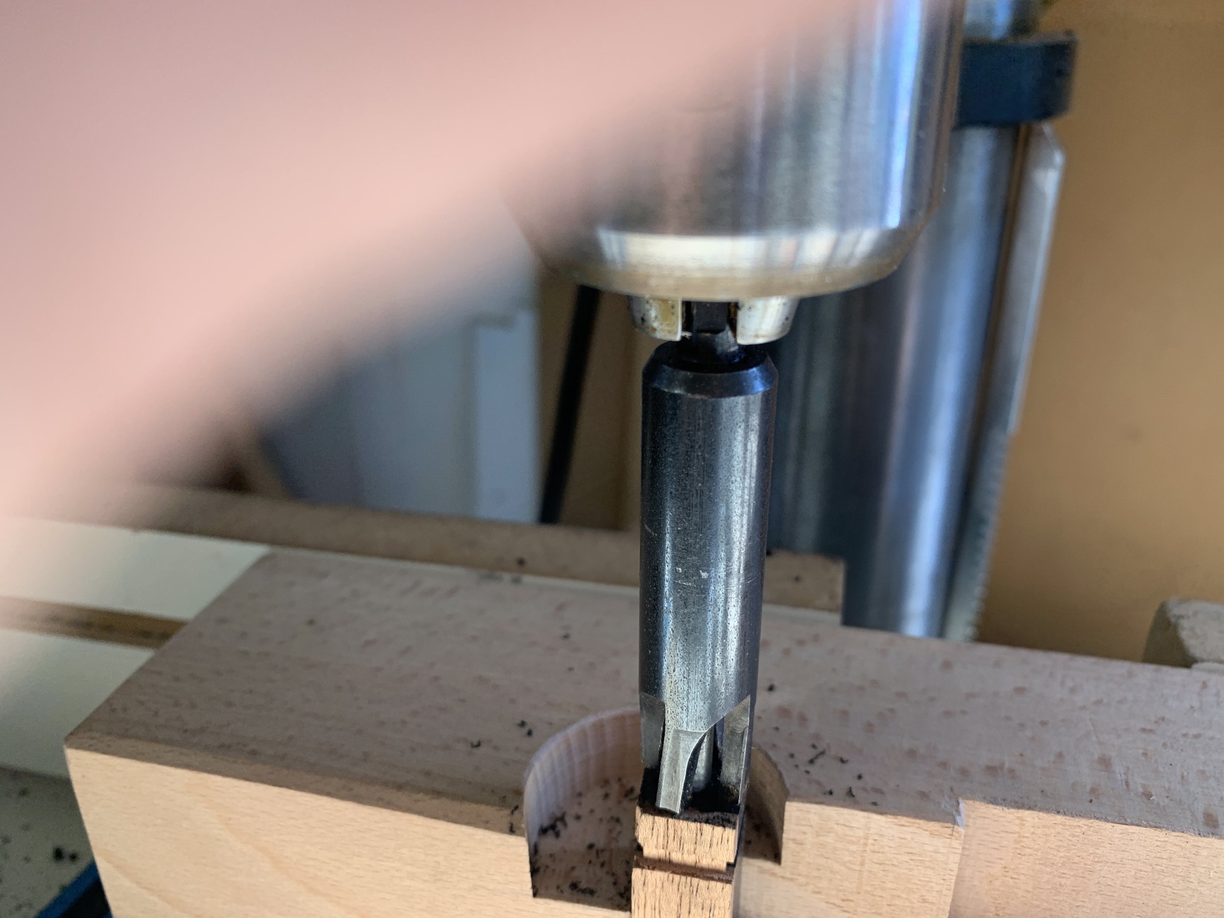
There’s more than one way to cut the tenons, I use a plug-cutter and a jig to hold the cross pin vertical.
Assemble the four parts of the plane using the Index Pins. Clamp securely to bring the cheeks and blocks snugly together.
Set the cross pin across the plane and mark where the shoulders are to be milled.
The portion of the cross pin inside the plane should be slightly smaller than the width of the midsection.
Get the tenons started using a table saw with the blade set no higher than 1/16”. Zero-in on the inside lines and cut around the pin as shown below. Cut the pin to length.
Normally, the cross pin is made from a solid piece of wood. Locate the smoothest side and mark it. This will be the side that rests on the blade.
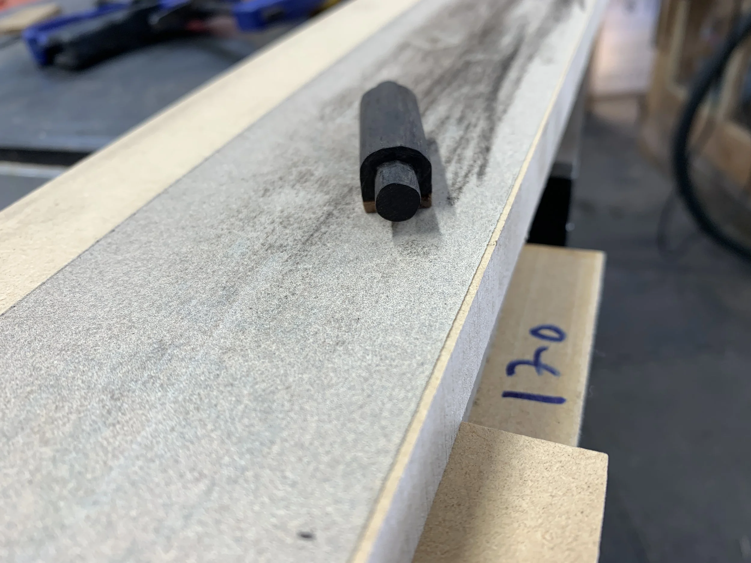
Place the pin in the jig (or whatever means used to hold the pin vertical) with the marked side facing you. Align the plug-cutter blades so they are centered on the pin. Make a small test cut. If it looks good, complete the cut being careful to not cut too deep. Flip the pin over, keeping the marked side facing you, and cut the other tenon.
The jig to hold the cross pin vertical.
Align the plug-cutter with the pin.
A small test cut.
Complete the cut.
Flip the pin over and cut the other tenon.
Trimming the tenons.
A chisel, saw, file, sandpaper or anything else you have can be used to trim the tenons to fit in the holes in the cheeks. Use the waste blocks for most of the process. Press the tenon into one of the holes and twist the cross pin. Shiny patches show where the tenon needs trimming. They should rotate easily with no wobble.
When finished with the waste block, assemble the plane with the cross pin and clamp securely. If the cross pin doesn’t move freely-but snugly, additional trimming is necessary.
Tools to trim the tenons.
Waste block.
Assembled plane clamped securely.
Locate the smoothest side of the cross pin and bevel or round-over the opposite side. This helps to locate the smooth side when setting the blade and wedge in the plane.
Mill the slot in the rear block for the chip breaker bolt
There are many ways to do this: hand tools, router table, router and jig, etc. I use the jig designed by David Finck and a hand-held router with a pattern bit.
A center line is drawn on the rear block sole which is matched to the center line on the jig. The block is placed, ramp down, on the jig at the line marked 3/4” and clamped in place. The jig with the block is clamped upside-down in a vise. A router with a pattern bit, slightly larger than the bolt head, is used to mill the slot.
Enlarging the escapement
This is optional. Mark the curve and shape it with a bandsaw and belt or spindle sander.
Start the curve 1/8” to 1/4” from the bottom.
Glue-up
Sand the insides of the cheeks, ramps and cross-pin.
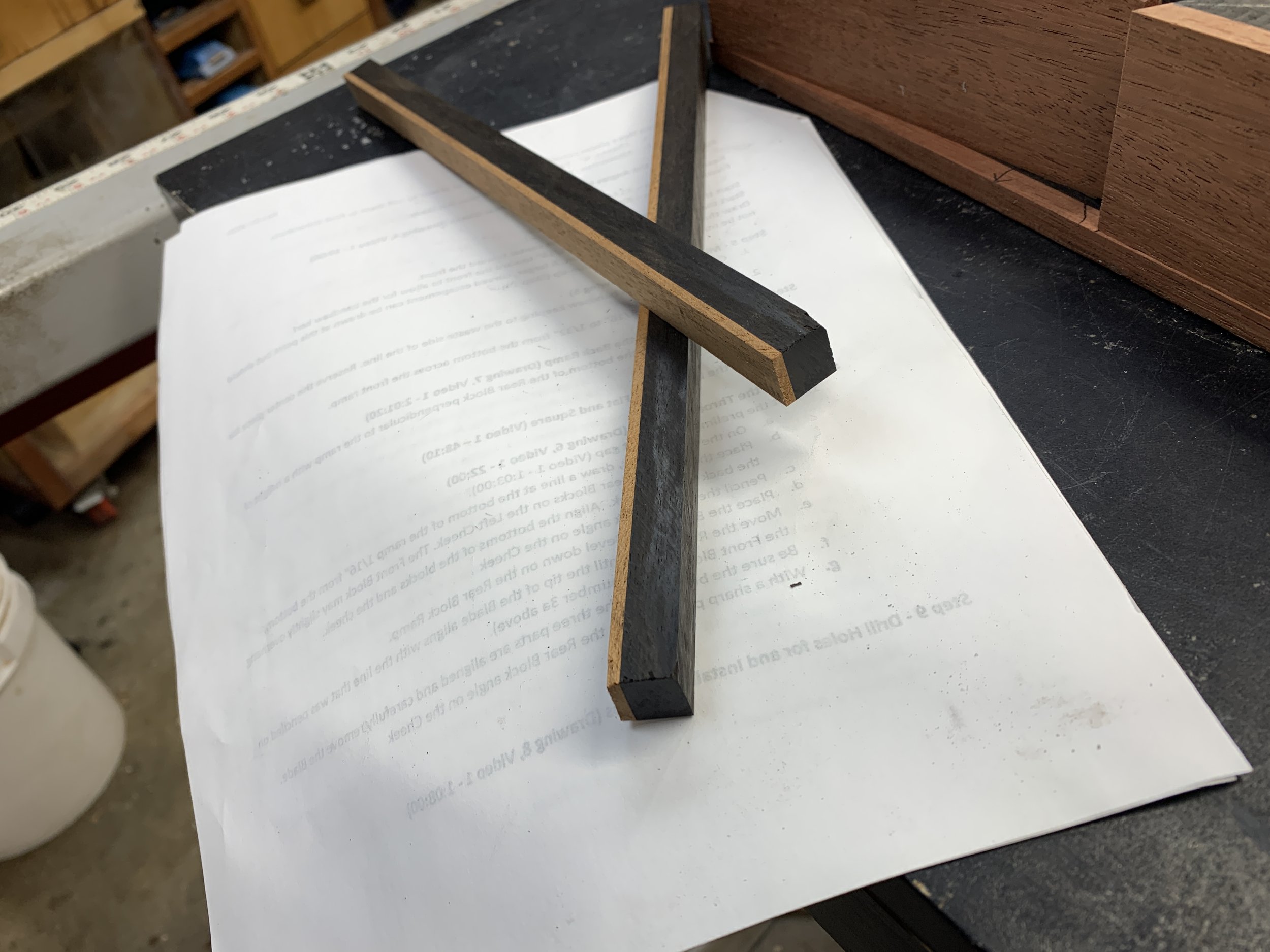
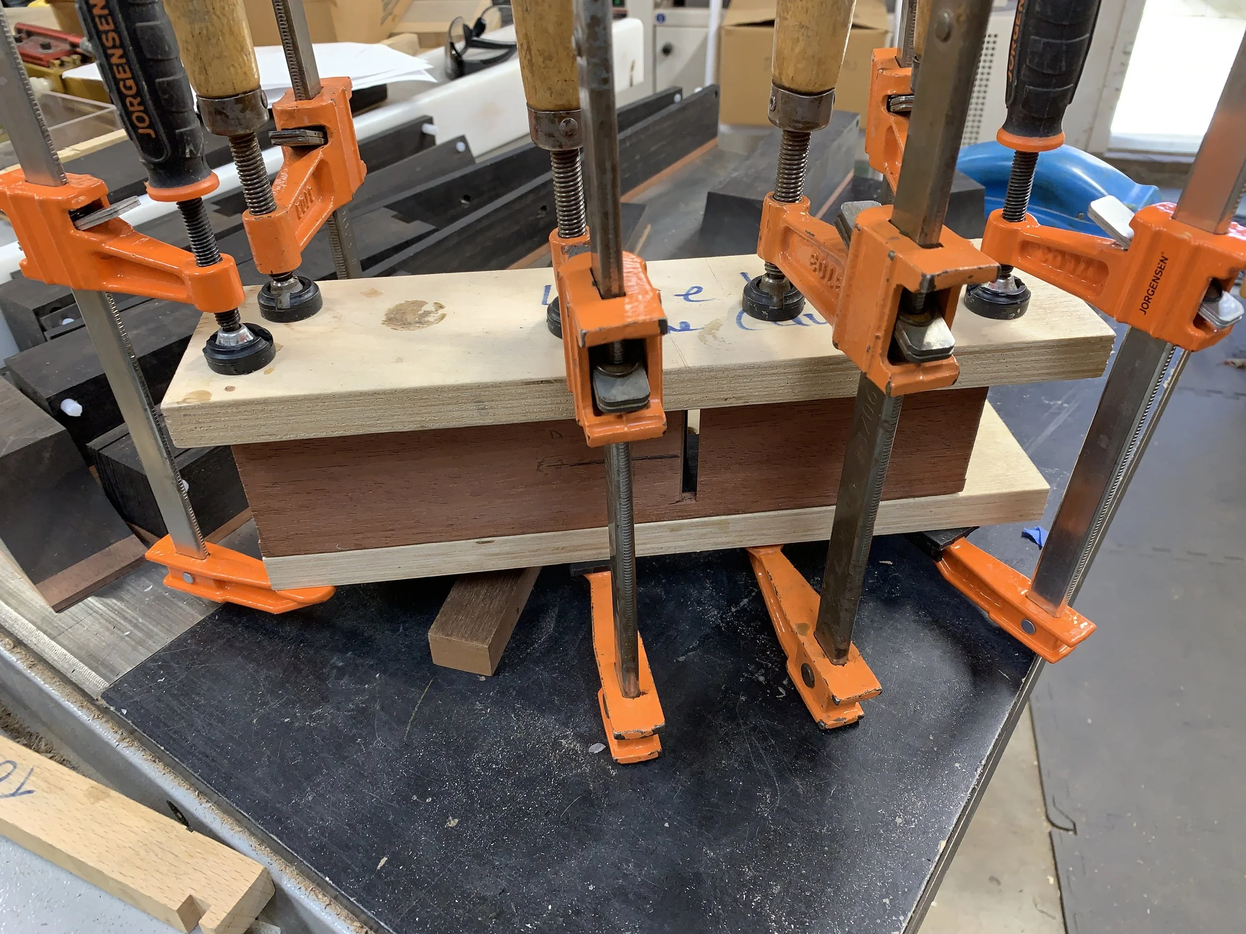
At least 6 clamps, two cauls and one alignment stick are needed. The alignment stick is thinner and longer than the mid-section, milled flat on one face and is used to ensure the sole is flat. It’s advisable to do a dry-clamping first to be sure the pieces will fit together well and the cross-pin will rotate. When clamping the alignment stick to the sole, place the clamps close to the ramps.
Using a chisel, ensure that neither the dowels nor the cross pin tenons protrude from the sides of the plane.
Dry-clamp steps: Assemble the plane and clamp the alignment stick in place ensuring it does not touch the cheeks. Place the cauls on the sides and clamp the assembly together at four of the places shown. Unclamp the alignment stick and use the clamps for the final two places.
Check the cross pin to be sure it moves freely.
If satisfied, proceed to the glue-up. Carefully remove any squeeze-out from the ramps and sole. Allow sufficient time for the glue to dry.
Smaller planes need 6 clamps. Larger planes need 2 to 4 more. The cauls and the alignment stick are longer than the plane.
Clamp placement for the alignment stick.
Clamp placement locations.
Tuning and adjusting
With the glue-up complete, tuning and adjusting can begin. This includes:
Making a temporary wedge used to put the plane under tension while flattening and squaring the sole, making a final wedge and aligning/adjusting the mouth.
After that, all that remains is shaping the plane.
Make the temporary wedge
The plane must be under pressure while making final adjustments to the sole. It is safer to do this without the blade in place, so a temporary wedge is used. The drawing below shows how to find the wedge angle.
Align the cross pin parallel to the back ramp. Use a ruler to measure the distance from the ramp to the bottom of the cross pin. This distance is “X” in the drawing. The “rise over run” of the angle is 1/4” over 2”.
When finished, the wedge should protrude in front of the cross pin by 1/4”.
Temporary wedge made from mahogany. Start with a blank longer than needed.
Plane the angled surface flat.
Insert the wedge in the plane with a minimal amount of pressure. Try to move the wedge side-to-side. If it moves, it’s not flat. Plane where you see the wedge pivoting on the cross pin.
Going forward, a hammer or two are required. The metal hammer is used to set the wedge. It can also be used to loosen the wedge, but will mar the plane, so I use a rawhide mallet for this.
Setting the wedge
Setting the wedge is a process of listening. Insert the wedge in the plane. Holding the plane in one hand, tap the wedge with the metal hammer. As you tap, the sound will rise in pitch. The wedge is then properly set. You may also feel the hammer bouncing off the wedge more as it sets.
The process is the same with the final wedge and blade.
To loosen the wedge, hit the back of the plane with the rawhide hammer.
Flatten and square the sole
Place the blade, bevel down, in the plane to see how close to the sole it touches the front ramp. It’s should be around 1/16”. Using a jointer, reduce this to 1/32”, then use sandpaper to remove any milling marks.
Two things to check first: The dowels and the cross pin are not protruding from the side and the jointer fence is square.
The jointer should be set to take very thin cuts, 1/64” if possible.
Before flattening the sole.
Fence needs to be square to the table.
This is an iterative process: Secure the wedge in the plane and make a pass or two over the jointer blades. Remove the wedge and place the blade back in the plane to check how close it is to the sole. Repeat until the blade is 1/32” from the sole.
After jointing. Note the mill marks.
Using 120 or 180 grit sandpaper on a flat surface, sand the sole to remove milling marks. Grip the plane in the middle and apply downward pressure there. Move the plane forward and come to a stop before lifting it. This process will help achieve a flat surface without rounding the ends.
After sanding.
Milling the final wedge
The final wedge is milled in the same way as the temporary wedge but with a couple extra steps: The end sitting near the edge of the blade needs to be rounded to a sharp point and the “hammered” end needs to be rounded to avoid cracking and ease of access.
For the final wedge, place the blade and chip breaker on the back ramp before measuring distance “X”.
Final wedge angle.
After bandsawing the angle, plane the ramp flat and test it the same way as the temporary wedge. Using sandpaper or another means, round the front edge of the wedge to a knife point.
The “hammered” end of the wedge is rounded to prevent splitting, and shaped to allow easy access to the blade.
Adjust and align the throat opening
With the blade in the plane, hold it up to a light to see where the throat needs adjustment. Using a file, as shown below, file the high spots. This is an iterative process. Go slowly and check your work often. Stop when the blade first bursts through the mouth. The goal is a very tight fit. Pressure from the wedge, when set, will open the mouth.
File the high spots.
File with at least a 5-degree angle towards the front of the plane.
At this point, you should have a well functioning plane. Sharpen the blade and make some shavings.
Shaping the plane
The first step is to bevel the sides of the plane at the sole. Mill to about 1/16” from the mouth.
Shaping is, of course, a matter of taste. I’m trying to copy the shape of a plane one of my students made and also trying to shape all four as closely as possible. The size difference may make this a bit difficult.
Another difficulty for these planes is that the blanks were only 2 inches high as I had to work with the ebony board I had. Normally I’d like to start with a blank that’s at least 2 1/2” tall as it allows more sweeping curves.
Another constraint is the cross-pin hole. There should be at least 1/4” of cheek left above the hole, 5/16” is better.
So, with all that to consider, I drew the shape on the jack plane and milled it with a bandsaw and oscillating belt sander.
One more item, the sole can be rounded at the back, but the front should have a crisp edge where it first contacts wood.
Sole sides beveled.
Approximate shape drawn on one plane.
Still a long way to go with the jack plane, but with the basic shape is done. I will try to match the other planes to it.
Matched the other three to the jack plane as best as I could. Have to admit that shaping is not my strongest suit.
Lots of different tools to shape the planes.
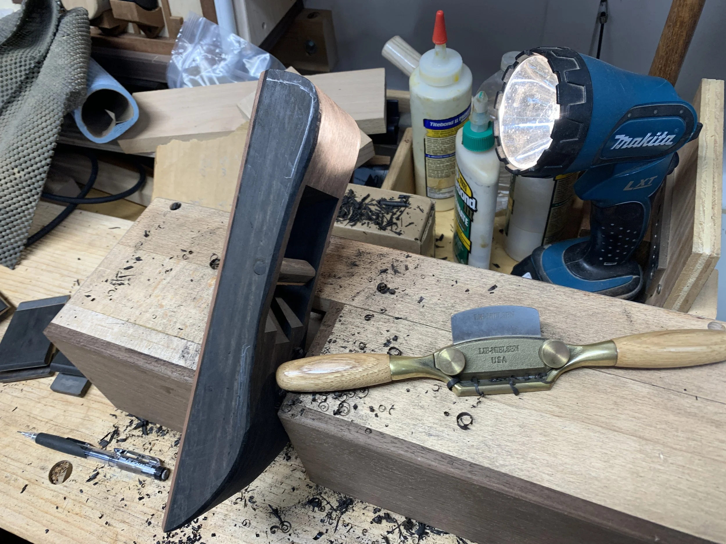
I wound up using a spokeshave and sandpaper.
Wiped it down with mineral spirits. May touch-it-up, but I think I’m satisfied. Most importantly, it’s comfortable to hold.
Finishing
I normally sand to 180 grit and put a coat of boiled linseed oil (BLO) on my planes. However, for these I’m going to use a technique learned from Brian Miller, a professional finisher.
Sand the wood to 320 grit. Apply a coat of BLO. Wet-sand with 2000 grit.
Wipe-off the BLO .
If applying more than one coat of BLO, only wet-sand after the first coat.
This doesn’t change the appearance of the wood but gives a wonderful soft feel to it.
Well, I got this far and ran into a problem. The BLO exposed some tear-out around the holes in the cheeks for the cross-pins, and I couldn’t leave it that way. After a bit of thought, decided to cover the holes with a rounded diamond shape. (Let’s keep this between us. If anyone else asks, the planes were designed this way.)
Jack plane
Smoother
Jointer and block plane


