DETAILED DRAWINGS:
As promised, here is a link to a set of detailed drawings for the treasure chest.
We will start this blog with the basic parts having been pre-milled. Each TC box requires one each of the front, back, and box-bottom and two of the sides. See Drawing 1 for the pre-milled dimensions.
All parts should eventually be sanded with 120 grit sandpaper. This can be done before or after the following steps thought it’s much easier to sand the inside faces before assembly.

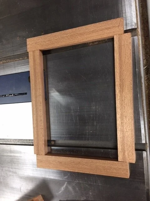
The Box: One front, one back, two sides and one box-bottom.
MATCH THE SIDES, DETERMINE INSIDE/OUTSIDE FACES AND ORIENTATION OF SIDES, BACK AND FRONT
The first operation in this process is one of aesthetics. It is not necessary, but will create a better looking TC.
Step 1: Match pairs of sides using grain pattern and color, determine the outside faces and which end is up.

Two examples of matched sides.
Step 2: For the front and back, determine the outside faces and which end is up.
The “paired” sides must be kept together going forward. The sides will be matched with fronts and backs later.
ORDER OF OPERATIONS
It is often beneficial to group operations together for all applicable parts. For example, every part of the TC, except the box-bottom, gets a 3/16” round over on at least two edges and doing the round over operation on all these parts at the same time makes sense. (Note: The roundover is the first operation for all the parts except the sides.) The processes shown below are in the order of the drawings and not intended to be a production plan.
THE FRONT (Drawing 2)
Step 1 - 3/16” round over on all edges. Note: Throughout the drawings, a red stripe indicates where to route the round over.

Route the end grain edges first and use a push block or a jig with a sacrificial fence to avoid tear out.

For routing the small edges, parts may be grouped together but must be held securely.

Use even/consistent pressure into the table and fence.
Step 2 - Mill the groove for the box-bottom.
Having determined the top and inside faces of the front, mill a groove in the inside face at the bottom of the parts. The groove is 3/16” wide, 1/4” deep and 3/16” from the bottom. We mill the groove at 3/16” as the box-bottom is made from 1/4” plywood (which is really 3/16”).
There are a few ways to achieve a 3/16” groove:
Often, one of the outside blades of a dado set will be 3/16”
Make two passes on the table saw using a regular 1/8” blade
Use a 3/16” router bit in a router table.

Groove for the box-bottom milled in the front.
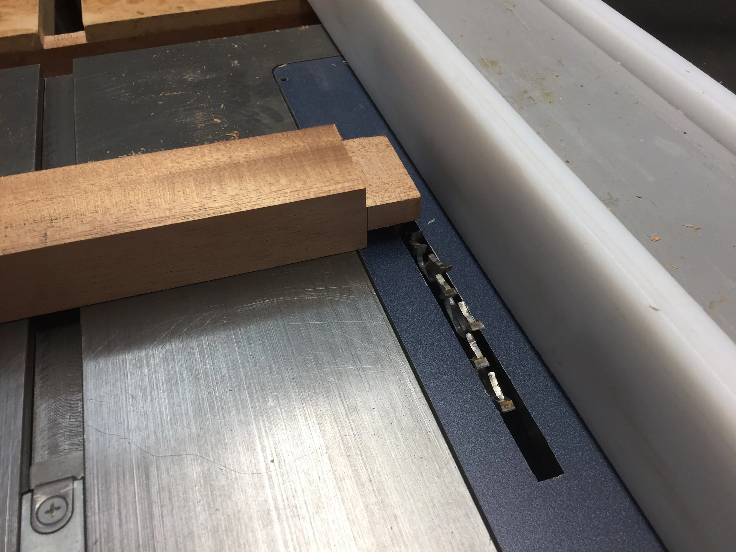
Step 3 - Mill the rabbets for the sides
One more process is required to finish the front. That is milling the 5/8” x 1/4” deep rabbets on the inside face to join the sides to it.
Regarding dado blades: Throughout this process, we use a box-joint dado set that cuts either a 1/4” or a 3/8” dado. For dados wider than 3/8”, more than one pass is required. We use this blade because it provides a very smooth flat cut.
- Set-up the table saw and dado blade to mill a 5/8” by 1/4” dado. Add a sacrificial fence to the miter gauge.
Regarding the 5/8” specification: This is an approximation. Though the sides are milled to a 5/8” thickness, it may not be exact. Also, wood moves and dimensions change. So the 5/8” rabbets need to be adjusted to fit, as closely as possible to the thickness of the sides.

Make test cuts in a piece of scrap wood to adjust the width of the cut to match the width of the sides.

Mill the rabbets on both ends of the inside face of the front

Sand the inside faces of the rabbets if necessary. The front is now finished.
THE BACK (Drawing 3)
Step 1 - 3/16” round over on the bottom edges.
Step 2 - Mill the groove for the box-bottom.

Groove for the box-bottom milled in the back using the same dimensions as the Front.
Step 3 - Route the 1/2” round over

Set-up the 1/2” round over bit in the router table.

Place the inside face of the back against the fence with the bottom facing up and mill the round-over.

Sand as necessary and ease the sharp point at the top. The back is now finished.
THE SIDES (Drawing 4A)
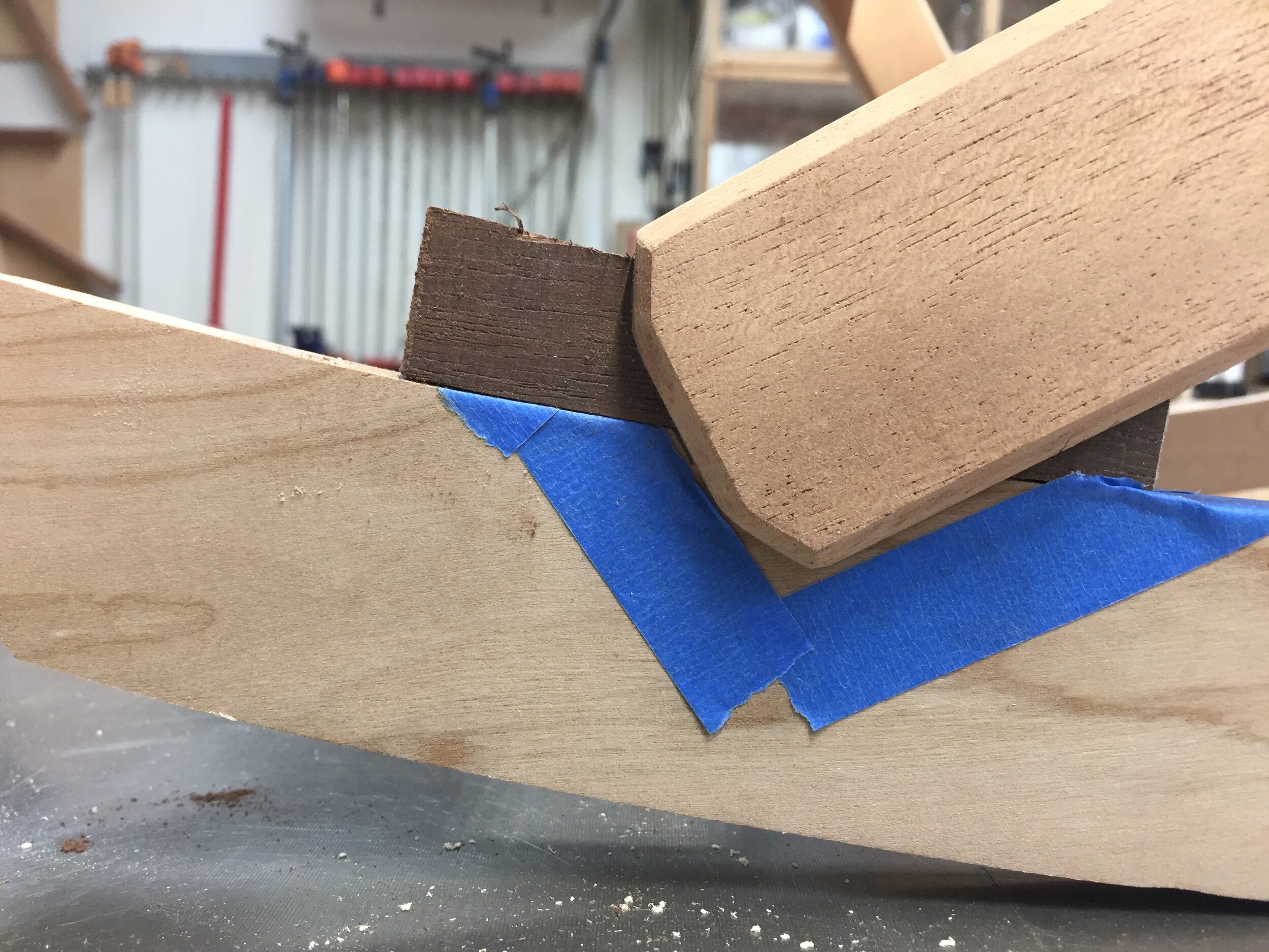
Step 1 - Route the stopped rabbet for the back.
Router table set-up
Use a 3/4” straight router bit.
Step A: Set up the bit in the router table so it will cut a 1/8” deep rabbet.
Step B: Adjust the fence so the rabbet will be 5/8” wide. Make test cuts and adjust this dimension to match the thickness of the back whose ends fit into the rabbets.
The rabbet is milled in each side to match the back. As the back has a curved top, the rabbet in the sides needs to match the curve.
Since it is a stopped-rabbet, stop-blocks need to be clamped to the router table fence at appropriate places.
Also, since the two sides are mirror images of each other, they require different set-ups for the stop-blocks.
ROUTE THE LEFT SIDE RABBET (left as in facing the front of the box)
Step A: Clamp the stop-block to the left side of the fence so the distance from the stop-block and the far edge of the router bit approximates the height of the back.

A completed back is used to position the stop-block.
Step B: Make a test cut and fit the end of a back into the dado. Adjust the stop-block as necessary so when the bottoms of the two parts are flush, there should be approximately 1/8” clearance at the curved end of the rabbet.
Step C: When the stop-block is properly placed, mill all of the left sides.
Step D: Clean-up the edge with sandpaper if necessary.

Apply consistent pressure down toward the table and forward into the fence.

Since the 3/4” bit leaves a small “hook” at the end of this step, after the part reaches the stop-block, pull the part out at an angle to remove the “hook.”

Left side rabbet milled.

Stopped rabbet shown with a finished back.
ROUTE THE RIGHT SIDE RABBET
Step A: Move the stop-block to the other side of the router table fence and align as described above.

Step B: With the inside face down and the bottom of the part to the right, wedge the corner of the side against the fence and stop-block as shown.

Step C: Keeping pressure towards the fence and the stop-block, feed the part into the router bit.

Step D: Feed the part to the left. Before the part moves past the router bit, add a backer-block to prevent tear-out.

Both rabbets are milled.
Step 2 - Mill the groove for the box bottom
Using a one of the techniques described above, mill a 3/16” groove in the inside face at the bottom of the sides. The groove is 1/4” deep and 3/16” from the bottom of the parts.
Milling the groove in the sides is a bit tricky as the two sides are not identical, but mirror images.

Step A: Hold the paired sides together with the bottom toward the table saw fence.

Step B: Separate the parts so the inside faces are pointed down.

Step C: Place the parts on the table saw with the inside face down and the bottom against the fence.

Step D: Mill the groove, one part at a time using the same dimensions as the Front.

The end result.
COMPLETING THE SIDES (Drawing 4B)
Step 3 - Route the 3/4” round over
To allow the lid to open properly, the top rear corner of the sides needs to be rounded-over.
Step A: Set-up a 3/4” round-over router bit in the router table.

Step B: With the back end of the side against the fence and the top of the side on the router table, feed both the left and right sides through the router bit. Use a push block or a jig with a sacrificial fence.


The result.
Step 4 - Drill the 1/4” hole for the hinge dowel pin
Drill a 1/4” hole in the upper rear corner of each side located 7/16” from the top and 7/16” from the rear.

Align the jig on a drill press table. Clamping the part down may provide a cleaner hole.
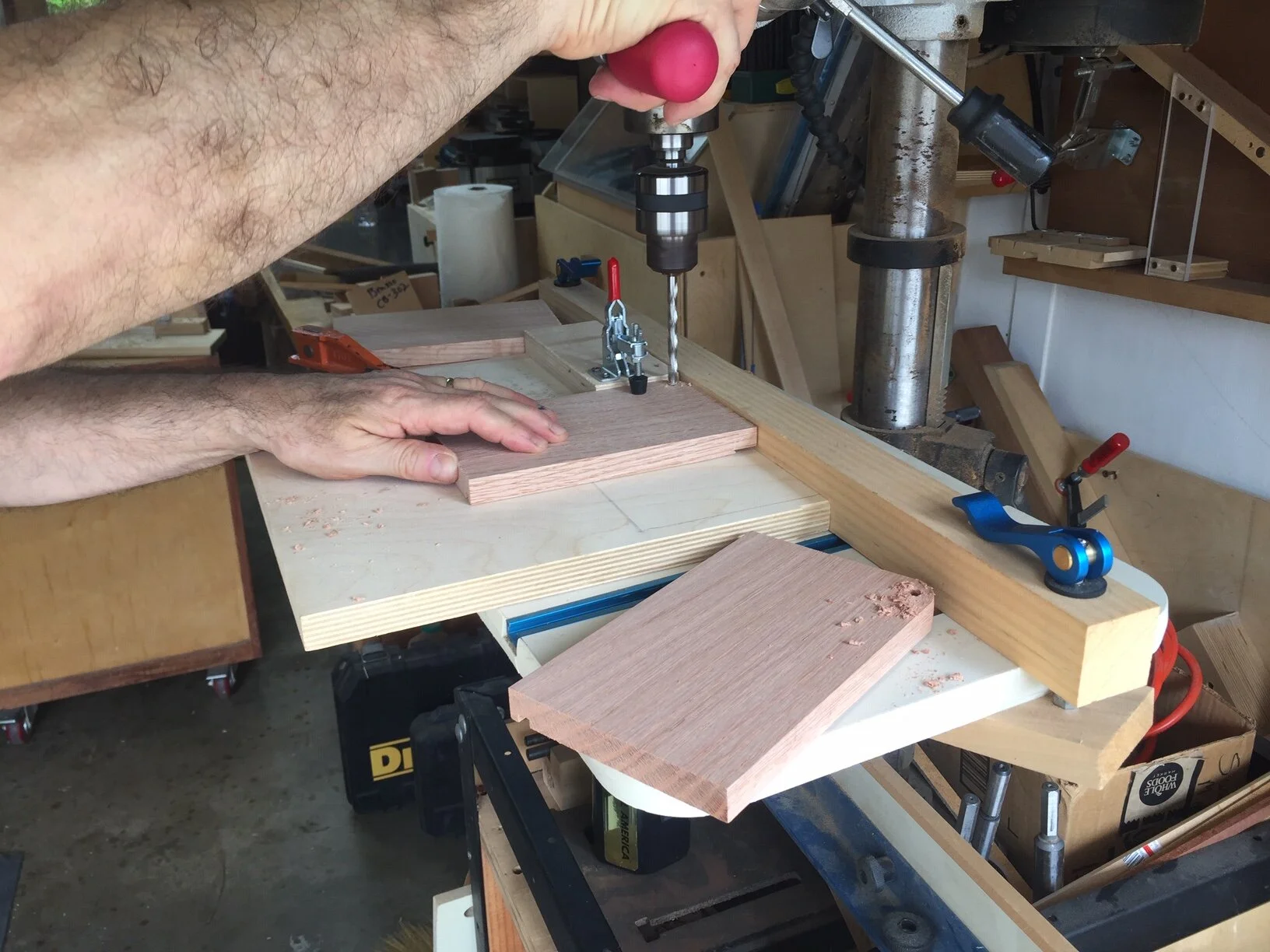
Rotate the sides to always drill into the outside face.
Step 5 - 3/16” ROUND-OVER OF THE SIDES
Refer to Drawing 4B for the edges to be rounded.


MATCH THE SIDES WITH A FRONT AND BACK
As mentioned before, this is not required, but will produce a nicer looking TC.

Example of matched sides, front and back.

MILL THE BOX-BOTTOM
From 1/4” plywood, mill the box-bottoms per the dimensions noted in Drawing 1. Clean up all edges with sandpaper.
READY FOR ASSEMBLY
Refer to Part 4 of this blog for box assembly instructions. If this will be done at a later date, be sure to keep the matched sets of parts together.